当前位置:网站首页>Experiment 5 8254 timing / counter application experiment [microcomputer principle] [experiment]
Experiment 5 8254 timing / counter application experiment [microcomputer principle] [experiment]
2022-06-25 01:24:00 【Sun star moon cloud】
experiment 5 8254 timing / Counter application experiment 【 Microcomputer principle 】【 experiment 】
Preface
The following contents are derived from the microcomputer principle experiment guide
For learning and communication only
Please read the article statement , By default, I agree with this statement
3.1 8254 timing / Counter application experiment
3.1.1 The experiment purpose
1、 Palm newspaper 8254 And application programming ;
2、 Palm evidence 8254 Typical application circuit connection ;
3、 Study 8254 stay PC Typical application methods in the system .
3.1.2 Experimental content
1、 A simple single pulse unit is discussed and tested , Press the microswitch to send a single pulse to the counter in turn , Observe the change of the new current count value of each pulse hour meter .
2、 Fixed time application and fixed test . Programming , application 8254 The timing function of , Produce a 1s The square wave , And observe with the oscilloscope function of the device .
3.1.3 Experimental principle
8254 yes Intel Programmable interval timer produced by the company . yes 8253 Improved type of , Than 8253 It has better performance .
8254 It has the following basic functions :
(1) Yes 3 Independent 16 Bit counter ;
(2) Each counter can be in binary or decimal system (BCD) Count ;
(3) Each counter can be programmed to work in 6 Two different ways of working ;
(4)8254 The maximum count frequency allowed for each counter is 10MHz(8253 by 2MHz);
(5)8254 There is a read back command (8253 No, ), In addition to being able to read out the contents of the current counting unit , The status register can also be read Rong .
(6) The counting pulse can be a regular clock signal , It can also be a random signal .
The formula of initial value of counting is n=fCLKi / fOUTi among fCLKi Is the frequency of the input clock pulse , fOUTi Is the frequency of the output waveform .
chart 3-1-1 yes 8254 Internal structure block diagram and pin diagram of , It is made with CPU The interface of 、 Internal control circuit and three counters .8255 Its working mode is as follows :
(1) The way 0: Count to 0 End output positive jump signal mode
(2) The way 1: Hardware can re trigger monostable mode .
(3) The way 2: Frequency generator mode ,
(4) The way 3: Square wave generator
(5) The way 4: Software triggered strobe mode
(6) The way 5: Hardware triggered strobe mode .

chart 3-1-18254 Internal interface and pins of
8254 There are two control words for : A way to set up a counter , It is called mode control word ; The other is used to set the read back command , It is called read back control word . These two control words share the same address , Distinguish by the identification bit . The format of mode control word is shown in table 3-1-1 Shown . The format of read back control word is shown in the table 3-1-2 Shown . When the control word is read back D4 Position as 0 when , Read back the control word D1-D2 The contents of the status register of the counter specified by bit will be latched into the status register . The format of the status word is shown in the table 3-1-3 Shown .

8254 The schematic diagram of the experimental circuit is shown in the figure below .

3.1.4 Experiment description and steps
1、 Counting application experiment
chart 3-1-2 For reference wiring diagram .OUT0 Can be connected to a LED, To observe the high and low level of its output . Put the counter 0 Set to mode 0, Count the initial value N At its discretion , Press single pulse simplex ( It is located in the middle of the bottom of the experimental platform ) The microswitch generates a single pulse to send CLK. Write a program to display counters on the screen 0 The current count of .
The experimental steps are as follows :
(1) Write the program according to the experimental content , Realization 8254 Yes KK1+ Response to the number of keystrokes
------------- Theoretical knowledge ------------
1、 Confirm the port address
IO Base address 0600H
XR1---A0
XR2---A1
 Address range 600H~603H
0# Counter port address :0600H
1# Counter port address :0602H
2# Counter port address :0604H
 Control register port address :0606H
2、 Determine the working mode and count the initial value
 Counter 0 Work in a way 0, The interrupt mode is generated after counting
 read
 Write
3、 Determine the control word
 Write
00 11 000 0
 read
00 00 000 0
4、 Initializer
A EQU 0600H
B EQU 0602H
C EQU 0604H
S EQU 0606H
;N=9; Count the initial value
CODE SEGMENT
ASSUME CS:CODE
; Initialize counter 0 Program
	MOV  AL,00110000B
	MOV DX,S
	OUT  DX,AL             ; Send control word
	MOV DX,A
	MOV  AL,09H						;9 =0000 1001
	OUT  DX,AL             ; Send low 8 position
	MOV  AL,00H						;9 =0000 0000
	OUT  DX,AL             ; Send high 8 position
; Read counter 0 Current count value to CX in
	MOV  AL,00000000B
	MOV DX,S
	OUT  DX,AL             ; Send control word
	MOV DX,A
	IN  AL,DX             ; Read low 8 position
	MOV  CL,AL
	IN  AL,DX             ; Send high 8 position
	MOV CH,AL
CODE ENDS
	END SRART
------------- Theoretical knowledge ------------
(2) Design the experimental circuit diagram , Complete the line connection .
(3) Open the electric board of the test box , Run the program , Press KK1+ The micro switch , Observe the count value and... Displayed on the screen after the switch is pressed LED The change of the lamp

2、 Timed application experiment
take 8254 The counter of 0 And counter 1 Both are set to mode 3, Use a signal source 1MHz As CLKO The clock ,OUTO Output for quilt 1ms square wave , Re pass CLK1 Input ,OUT1 Output 1s square wave .
The experimental steps :
(1) The wiring diagram is shown in the figure 3-1-3 Shown ,
(2) According to the experimental content , Write the experimental program , Compiled 、 Load the system after the link is not mentioned
------------- Theoretical knowledge ------------
1、 Confirm the port address
IO Base address 0600H
XR1---A0
XR2---A1
 Address range 600H~603H
0# Counter port address :6C0H
1# Counter port address :6C2H
2# Counter port address :6C4H
 Control register port address :6C6H
2、 Determine the working mode and count the initial value
 Counter 0 Work in a way 3, Square wave generator
 Count the initial value = Input frequency / output frequency
   1000=1M /1000


 Counter 1 Set to mode 3, Square wave generator
 Count the initial value = Input frequency / output frequency
	1   =1000    /1000
3、 Determine the control word
00 11 011 0
01 11 011 0
4、 Initializer
A EQU 06C0H
B EQU 06C2H
C EQU 06C4H
S EQU 06C6H
CODE SEGMENT
ASSUME CS:CODE
; Initialize counter 0
	MOV  AL,00110110B
	MOV DX,S
	OUT  DX,AL             ; Send control word
	MOV DX,A
	MOV  AL,03E8H						;1000 =0000 03e8
	OUT  DX,AL             ; Send low 8 position
	MOV  AL,0H							;1000 =0000 0000
	OUT  DX,AL             ; Send high 8 position
; Initialize counter 1
	MOV  AL,01110110B
	MOV DX,S
	OUT  DX,AL             ; Send control word
	MOV DX,B
	MOV  AL,03E8H						;1000 =0000 03e8
	OUT  DX,AL             ; Send low 8 position
	MOV  AL,0H							;1000 =0000 0000
	OUT  DX,AL             ; Send high 8 position
CODE ENDS
	END SRART
------------- Theoretical knowledge ------------
(3) single click 【RUN】 Button , Run the experimental program ,8254 Of OUTI Will be output 1 The square wave , You can observe with the built-in detector function of the software .
(4) The method of observing waveforms with an oscilloscope : Click... In the virtual instrument menu 【 Oscilloscope 】 Button or directly click on the toolbar 【】 button , Click on the newly popped up oscilloscope interface 【】 Button to run the oscilloscope , You can observe OUT1 Output waveform .
The results of this experiment are shown in Figure 3-1-4 Shown ,
3.1.5 Experimental tips
1. Our... On the test box I/0 The base address is 0600H,CS Pick up IOY0 The signal line .
2. In the experiment 1 In the counting application experiment , The initial value is not easy to be too large (<10).
3. take OUT0 Pick up LED The lamp , The counting operation can be observed .LED The lamp is active at low level , Therefore, the lamp is off during counting in the experiment , The counting end light is on .
Last
Please read the article statement , By default, I agree with this statement
Reward channels 
边栏推荐
- 脱氧核糖核酸酶I中英文说明书
- Bi-sql top
- 天书夜读笔记——深入虚函数virtual
- lnmp环境安装ffmpeg,并在Yii2中使用
- How about compass stock trading software? Is it safe?
- sql 聚合函数对 null 的处理[通俗易懂]
- Programmer: did you spend all your savings to buy a house in Shenzhen? Or return to Changsha to live a "surplus" life?
- PMP考试“临门一脚”如何踢得漂亮?
- Tianshu night reading notes -- memory paging mechanism
- C语言边界计算和不对称边界
猜你喜欢

"One good programmer is worth five ordinary programmers!"

Bi SQL constraints

Abnova 5-methylcytosine polyclonal antibody
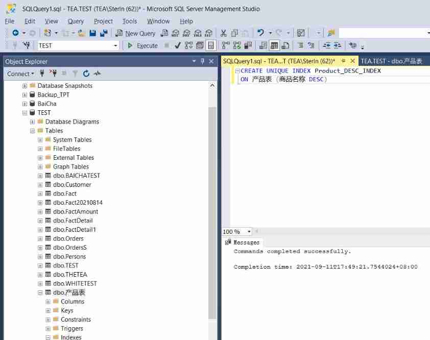
Bi-sql index
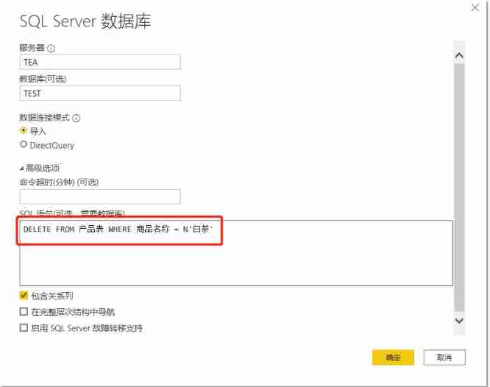
Bi-sql delete

Bi SQL alias

Hands on data analysis data modeling and model evaluation

论文翻译 | RandLA-Net: Efficient Semantic Segmentation of Large-Scale Point Clouds
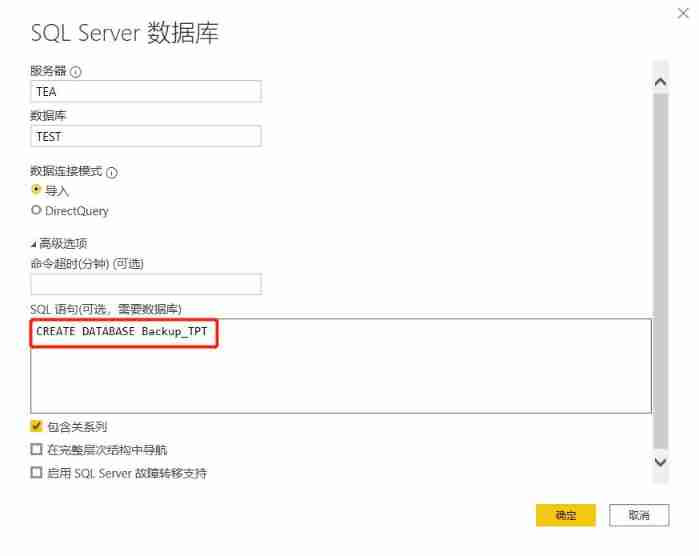
Bi-sql create

汇编语言(2)基础知识-debug
随机推荐
yasea apk 下载 镜像
弹性蛋白酶中英文说明书
Bi-sql - different join
Tianshu night reading notes -- disassembly engine xde32
Hands on data analysis data modeling and model evaluation
搜索二维矩阵[二分巧用 + 记录不同于插入二分的解法]
AUTOCAD——两种延伸方式
After the college entrance examination, the following four situations will inevitably occur:
AssertionError: CUDA unavailable, invalid device 0 requested
How to prepare for the last day of tomorrow's exam? Complete compilation of the introduction to the second building test site
论文翻译 | RandLA-Net: Efficient Semantic Segmentation of Large-Scale Point Clouds
MySQL gets the primary key and table structure of the table
Deploy a production cluster using Loki microservice pattern
Tencent cloud wecity Industry joint collaborative innovation to celebrate the New Year!
sql 聚合函数对 null 的处理[通俗易懂]
Programmer: did you spend all your savings to buy a house in Shenzhen? Or return to Changsha to live a "surplus" life?
期望与方差
Bi-sql index
Go language operators (under Lesson 8)
天书夜读笔记——8.4 diskperf反汇编