当前位置:网站首页>Functions and basic structure of CPU
Functions and basic structure of CPU
2022-06-23 06:35:00 【Picchu moving forward】
The article is written by observing the principle of Kingway computer composition
a central processor CPU
1.CPU Basic function
- CPU: a central processor
- CPU It consists of an arithmetic unit and a controller
- When you use a computer to solve a problem, write a program for it
- Program is a Command sequence , It tells the computer what to do , Where to find the data to operate on
- Once the program is loaded into memory , The computer can automatically complete the task of fetching and executing instructions

CPU Other features :
Handling interrupts :
① Control the input and output of the program , That means controlling the host and IO Exchange information of equipment , For example, our program is running , To give an input from can let the program continue to run , otherwise , The program will get stuck , This applies to handling interrupts
② Bus management , Request handling of exceptions and special cases during operation


2. Workflow
Let's first review the composition of the controller , The following knowledge needs to be used 
The first step is to take the finger
According to the program counter PC Specified main memory address , From main memory ( Or cache ) Read instruction , Place in instruction register IR
reflection : After the program starts executing , It will execute the program according to the relationship of instructions , So who gave the first instruction ?
For example, we installed on the computer QQ, When we want to run , Double click on it , Because we installed QQ When , It is installed on the hard disk , When you double-click , The operating system will transfer the program from the hard disk to the memory , The place to be transferred to memory is not fixed , Because memory is dynamically managed , That is to say, the location where the first instruction at the beginning of a program is stored is controlled by the operating system
We know that after taking out the instruction , You must want to do the corresponding operation , But we must know what to do first , That is, the meaning of the instruction code , To operate , So the next step is decoding .
The second step is decoding
according to IR The instructions in , Combined with the instruction system specification , Decomposing the opcode of an instruction 、 Address code, etc
opcode —— Indicate what to do
Address code —— Indicates how to get operands 、 How to save the result and how to form the subsequent instruction address
Step 3
Step 4 write back
Save the calculation results to main memory ( Or cache )
Step 5 interrupt
Respond to external requests
The next step is the cycle of these steps
This is the picture below CPU workflow 
3.CPU Basic composition of

1. Arithmetic unit

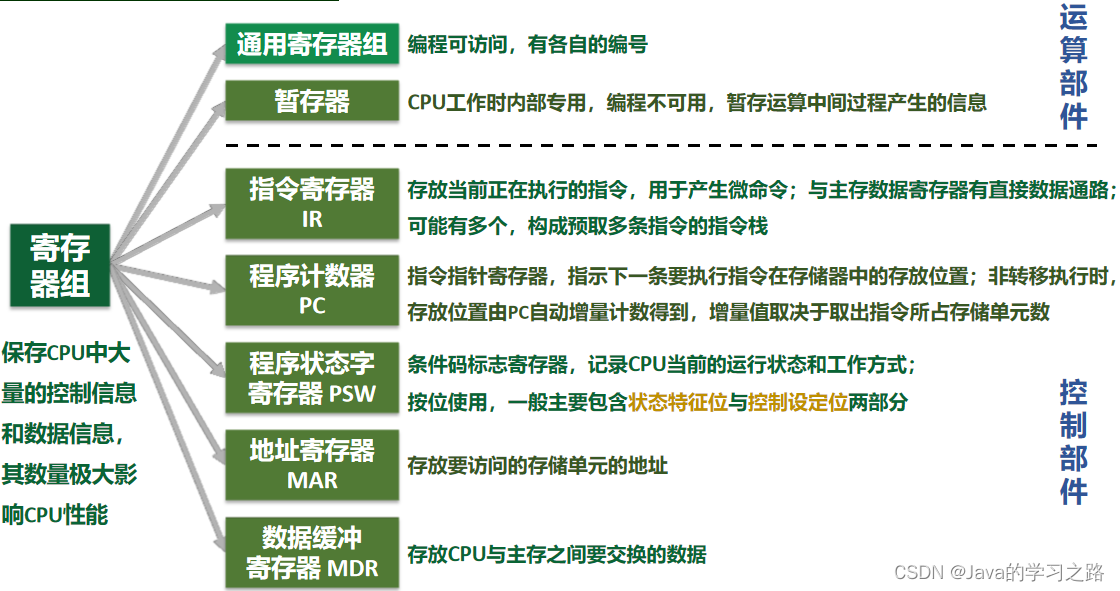
2. Register group
3. Control unit
seeing the name of a thing one thinks of its function , The arithmetic unit is used to do arithmetic , Then the control part must be used to control
The control unit is mainly used to decode instructions , And send out control signals for various operations required to complete the command function , For example, tell each component , Which components need to be operated , What specific operations should be carried out
We know that everyone has a different point of view , Therefore, different people have different feelings about the same thing , alike , The working process of the computer is different from different angles .
- From the user's point of view : The working process of a computer is the continuous execution of a sequence of instructions
- From the internal implementation mechanism : The working process of a computer is the transmission of information under control commands , It is the process of integrating control flow and information flow
For control components , The most important is the control command ( Micro command ) Generating parts 
It is obvious who will execute first , There must be a sequence , In stages , There should be a time signal , Here, it is controlled by the timing system
4. Sequential systems
Sync : There is a definite time limit for doing something , When will it start , When will it end 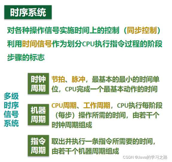
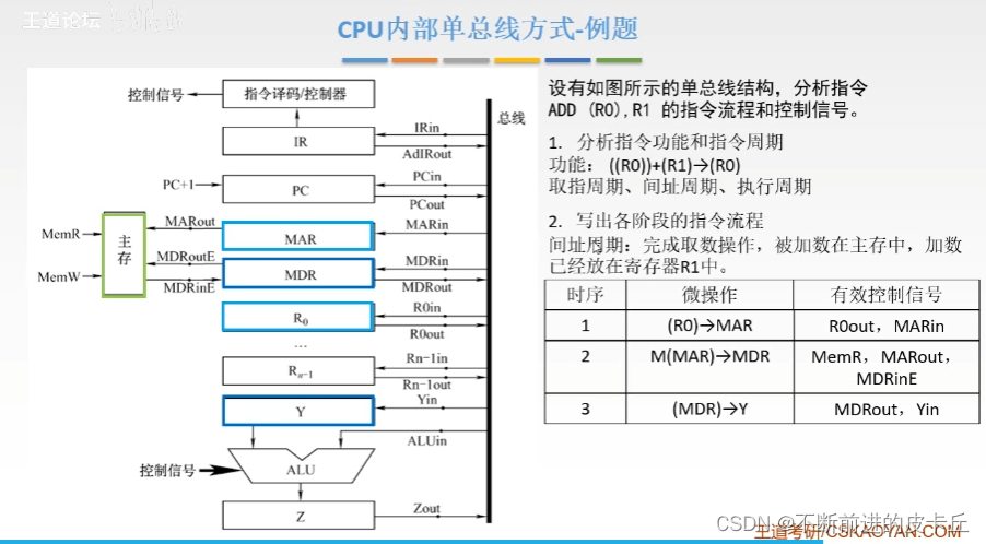
5.CPU Internal data path structure

- CPU Internal single bus mode : Connect the input and output of all registers to a common path , Only one component can transmit data at a time
- If connected directly with wires , It is equivalent to multiple registers simultaneously and all the way to ALU To transmit data ----> The accumulated signal is obtained at each input , It can't tell who is sending it data now

- There are four general purpose registers ,R0 To R3, Used to store operands ( Source operands , Destination operands , In the middle ) And various address information .
- If you perform an addition operation , Select two operands to add ( In two registers ), The resulting structure is returned to one of the registers (R2), that R2 The original content will be replaced


4. Instruction cycle and its data flow

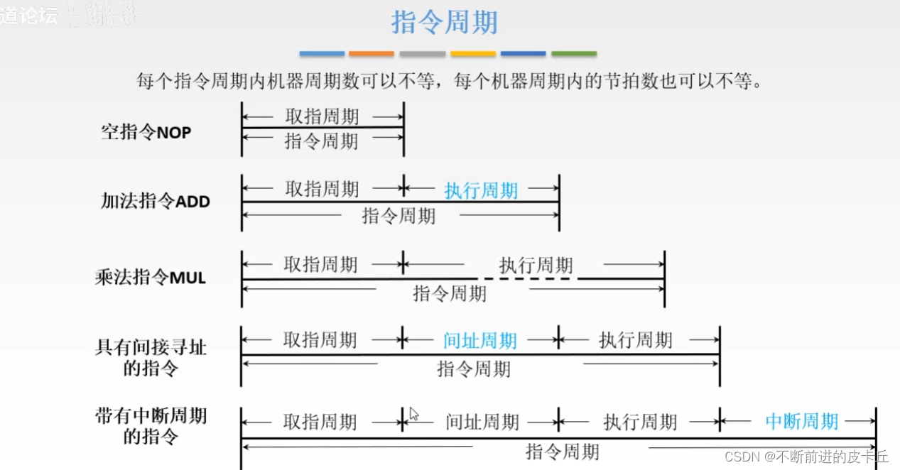
We know that instructions have different cycles , We can use triggers to determine which cycle the instruction is in 
The address of the instruction is placed in PC in ,CPU Communication with the memory depends on MAR and MDR


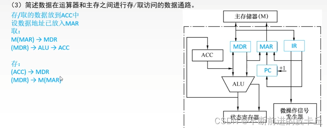
5. Data access
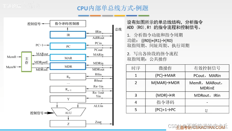
5.1CPU Internal single bus mode
- Data access : The transfer path of data between functional units
- The basic structure of data path :
- ①CPU Internal single bus mode
- ②CPU Internal multi bus mode
- ③ Dedicated data path mode
Single bus mode : Each component is connected to the bus , But the parts are not connected
The connection mode between each component and the bus is controlled by a control signal that can control the on-off of the signal
practice


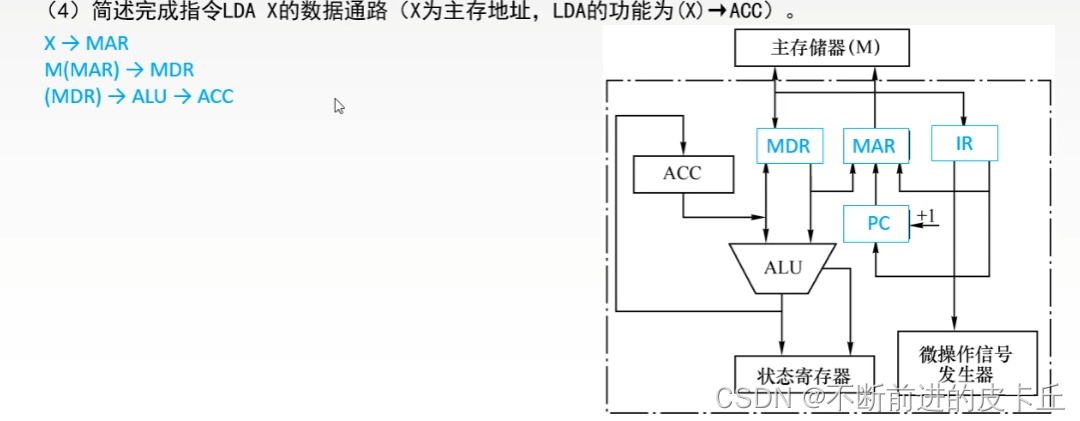
5.2 Dedicated data path


6. Function and working principle of the controller

6.1 Structure and function of the controller

The controller is the command center of the computer system , The main functions of the controller are as follows :
- Take an instruction from main memory , And indicate the position of the next instruction in main memory
- Decode or test instructions , Generate the corresponding operation control signal , In order to start the specified operation
- Command and control CPU, Main memory , The direction of data flow between input and output devices

CU The design of the : - Hardwired ( Combinational logic circuit + trigger )
- Microprograms
6.2 Hardwired controllers


Design steps
- ① Analyze the micromanipulation sequence of each stage
- ② choice CPU Control mode of
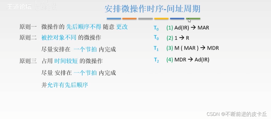
- ③ Schedule micro operations
- ④ Circuit design
6.2.1 CPU The control mode


6.2.2 The principle of scheduling micro operations

Unrelated operations can be scheduled to be completed at the same time 

6.2.3 Combinatorial logic design
Design steps
- List the operation schedule
- Write the simplest expression of micro operation command
- Draw a logic diagram
边栏推荐
- RF content learning
- 百度URL參數之LINK?URL參數加密解密研究(代碼實例)
- Simple about fastdfs
- Link of Baidu URL Parameters? Recherche sur le chiffrement et le décryptage des paramètres d'URL (exemple de Code)
- Day_12 传智健康项目-JasperReports
- 解析创客教育中的个性化学习进度
- Word pattern for leetcode topic analysis
- (1)基础学习——vim编辑器常用快捷操作命令
- Design scheme of Small PLC based on t5l1
- 索引——MySQL
猜你喜欢

如何查看本机IP

Docker实战 -- 部署Redis集群与部署微服务项目

mongodb 4. X binding multiple IP startup errors

Gplearn appears assignment destination is read only
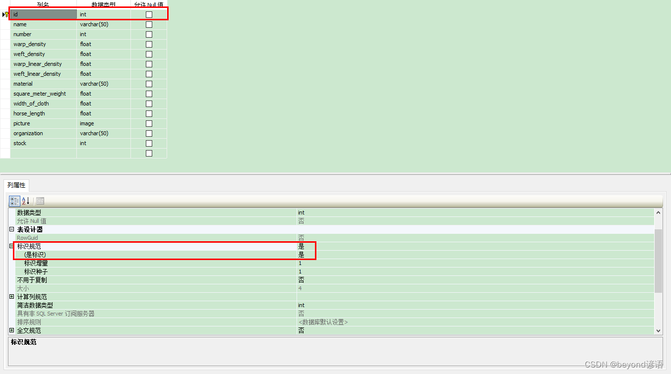
11、 Realization of textile fabric off shelf function
![[vivado] xilinxcedstore introduction](/img/c7/4f203d125ddb18378398a7eaeffaf5.png)
[vivado] xilinxcedstore introduction

Steam教育对国内大学生的影响力

Day_ 11 smart communication health project - graphic report and poi Report

Difference between MySQL read committed and repeatability

业务逻辑安全思路总结
随机推荐
[DaVinci developer topic] -41-app how SWC reads and writes NVM block data
Pyqt5 setting window top left Icon
Day_ 12 smart health project jasperreports
C语言 踩坑:文档编码错误,导致base64中文编码错误
Illuminate\support\collection de duplication unique list de duplication
【Leetcode】431. Encode n-ary tree to binary tree (difficult)
mysql读已提交和可重复度区别
Day_ 13 smart health project - Chapter 13
mysql如何将日期转为数字
mongodb 4. X binding multiple IP startup errors
Smart port: how to realize intelligent port supervision based on the national standard gb28181 protocol easygbs?
Day_12 传智健康项目-JasperReports
如何实现与FDA保持邮件通信安全加密?
WordPress Core 5.8.2 - 'WP_ Query'SQL injection
phpStudy设置301重定向
Golang regular regexp package use -04- use regular replacement (replaceall(), replaceallliteral(), replaceallfunc())
Day_02 传智健康项目-预约管理-检查项管理
解析创客教育中的个性化学习进度
程序员的真实想法 | 每日趣闻
c#数据库报错问题大家帮我看看吧