当前位置:网站首页>LETV group payment system architecture sharing for processing 100000 high concurrent orders per second
LETV group payment system architecture sharing for processing 100000 high concurrent orders per second
2022-06-22 16:42:00 【MarshalEagle】
With the continuous upgrading of leeco hardware rush purchase , LETV group is facing a 100 - or even 1000 fold increase in the demand pressure for payment . As the last link of commodity purchase , It is particularly important to ensure that users complete the payment quickly and stably . So in 15 year 11 month , We have comprehensively upgraded the architecture of the entire payment system , So it has stable processing per second 10 Million orders . It provides a strong support for various forms of rush buying and seckill activities of LETV ecology .
One 、 Warehouse sub table
stay redis,memcached In the Internet age when caching systems are popular , Building a system that supports 100000 reads per second is not complicated , It's nothing more than extending the cache node through a consistent hash , Horizontal expansion web The server etc. . The payment system has to process 100000 orders per second , What is needed is hundreds of thousands of database updates per second (insert Add update), This is an impossible task on any independent database , So the first thing we need to do is to check the order form ( abbreviation order) Divide the database and tables .
When doing database operations , There are usually users ID( abbreviation uid) Field , So we choose to uid Divide the database and tables .
We chose the strategy of sub Treasury “ Binary tree branch ”, So-called “ Binary tree branch ” refer to : When we are expanding the database , It's all about 2 To expand the capacity . such as :1 Taiwan expanded to 2 platform ,2 Taiwan expanded to 4 platform ,4 Taiwan expanded to 8 platform , And so on . The advantages of this method are , When we are expanding the capacity , just DBA Perform table level data synchronization , You don't need to write scripts to synchronize row level data .
It is not enough to have a sub - Treasury , After continuous stress testing, we found that , In the same database , The efficiency of concurrent updating multiple tables is much higher than that of concurrent updating one table , So in each sub database, we will order Table split into 10 Share :order_0,order_1,….,order_9.
Finally, we put order The watch is on 8 Of the sub libraries ( Number 1 To 8, They correspond to each other DB1 To DB8), In each sub warehouse 10 A minute table ( Number 0 To 9, They correspond to each other order_0 To order_9), The deployment structure is shown in the following figure :
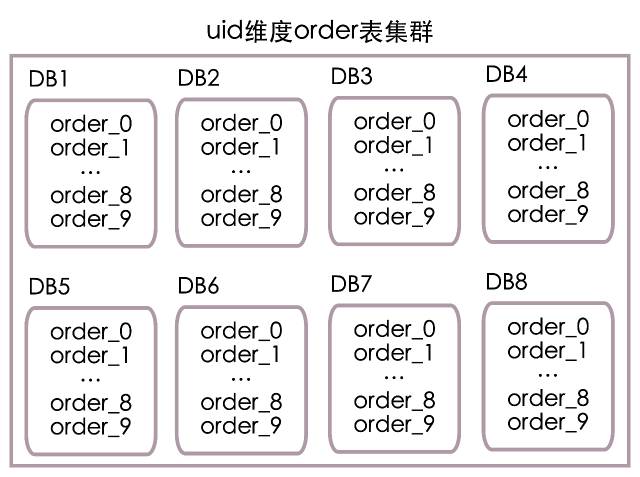
according to uid Calculate database number :
Database number = (uid / 10) % 8 + 1
according to uid Calculation sheet No :
Table number = uid % 10
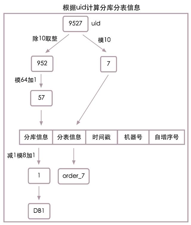
When uid=9527 when , According to the algorithm above , Is actually the uid It's divided into two parts 952 and 7, among 952 model 8 Add 1 be equal to 1 Number the database , and 7 Is the table number . therefore uid=9527 The order information needs to go to DB1 In the library order_7 Look up . See the following figure for the specific algorithm flow :

With the structure and algorithm of sub database and sub table, the last step is to find the implementation tool of sub database and sub table , At present, there are about two types of sub database and sub table tools on the market :
- Client sub database and sub table , Complete database and table splitting on the client , Direct connection database
- Use database and table splitting middleware , Client connected database and table middleware , The middleware completes the operations of dividing databases and tables
Both types of tools are available on the market , Here's not a list , Overall, these two types of tools have advantages and disadvantages . Because the client is directly connected to the database , Therefore, the performance is higher than that of the database and table middleware 15% To 20%. The use of database and table based middleware has unified middleware management , Separate database and table operations from clients , Clearer module division , Easy DBA Unified management .
We choose to divide databases and tables on the client side , Because we have developed and open source a set of data layer access framework , Its code name is “ Mango. ”, Mango framework natively supports the function of dividing databases and tables , And the configuration is very simple .
- Mango homepage :mango.jfaster.org
- Mango source code :github.com/jfaster/mango
Two 、 Order ID
Order system ID Must have globally unique characteristics , The simplest way is to use the sequence of the database , Each operation can obtain a globally unique auto increment ID, If you want to support processing per second 10 Ten thousand orders , That will need to generate at least 10 Ten thousand orders ID, Generate auto increment through database ID Obviously, the above requirements cannot be fulfilled . So we can only get globally unique orders through memory calculation ID.
JAVA The most famous one in the field ID Should be UUID 了 , however UUID Too long and contains letters , Not suitable as an order ID. Through repeated comparison and screening , We learned from Twitter Of Snowflake Algorithm , It realizes global uniqueness ID. Here is the order ID Simplified structure diagram :

The picture above is divided into 3 Parts of :
- Time stamp
Here, the granularity of timestamp is in the order of milliseconds , Generate order ID when , Use System.currentTimeMillis() As a time stamp .
- Machine number
Each order server will be assigned a unique number , Generate order ID when , Directly use this unique number as the machine number .
- Auto increment No
When there are multiple orders generated in the same millisecond on the same server ID The request of , This sequence number will be automatically increased in the current milliseconds , This sequence number continues from... For the next millisecond 0 Start . For example, on the same server in the same millisecond 3 Generate an order ID Request , this 3 Order per order ID The self incrementing serial numbers of will be 0,1,2.
above 3 A combination of parts , We can quickly generate globally unique orders ID. But it's not enough to be unique , Most of the time, we will only follow the order ID Directly query the order information , At this time, there is no uid, We don't know which sub database to query in the sub table , Traverse all tables of all libraries ? This is obviously not going to work . So we need to add the information of sub database and sub table to the order ID On , The following is the order with sub warehouse and sub table information ID Simplified structure chart :

We are generating global orders ID The header adds sub database and sub table information , So only according to the order ID, We can also quickly query the corresponding order information .
What are the specific contents of sub database and sub table information ? The first part discusses , We have arranged the order form according to uid The dimension is split into 8 A database , Every database 10 A watch , The simplest database and table information only needs a length of 2 String can be stored , The first 1 Bit store database number , Value range 1 To 8, The first 2 Bit storage table number , Value range 0 To 9.
Or according to the first part uid Algorithm for calculating database number and table number , When uid=9527 when , Sub database information =1, Sub table information =7, Combine them , The two digit sub database sub table information is ”17”. See the following figure for the specific algorithm flow :

There is no problem in using the table number as the sub table information , But there are hidden dangers in using database number as sub database information , Consider future capacity expansion requirements , We need to 8 The library is expanded to 16 library , At this time, the value range is 1 To 8 The sub database information of will not be able to support 1 To 16 The sub database scene of , Sub database routing will not complete correctly , We abbreviate the appeal problem as the loss of sub database information accuracy .
In order to solve the problem of accuracy loss of sub database information , We need to redundancy the accuracy of sub database information , That is, the sub database information we save now should support future capacity expansion . Here we assume that we will eventually expand to 64 Station database , So the new sub database information algorithm is :
Sub database information = (uid / 10) % 64 + 1
When uid=9527 when , According to the new algorithm , Sub database information =57, there 57 Is not a real database number , It redundantly extends to 64 Accuracy of sub database information in a database . We only have 8 Station database , The actual database number needs to be calculated according to the following formula :
Actual database number = ( Sub database information - 1) % 8 + 1
When uid=9527 when , Sub database information =57, Actual database number =1, Sub database sub table information =”577”.
Because we choose the module 64 To save the sub database information after accuracy redundancy , The length of saving sub database information is determined by 1 Change into 2, The length of the last sub database and sub table information is 3. See the following figure for the specific algorithm flow :
As shown in the figure above , The module is used to calculate the sub database information 64 The method redundancy the accuracy of sub database information , In this way, when our system needs to be expanded to 16 library ,32 library ,64 No more problems with the library .
The order above ID The structure can well meet our current and future expansion needs , But given the uncertainty of the business , We are placing an order ID At the front of the 1 Bit is used to identify the order ID Version of , This version number belongs to redundant data , It is not used at present . Here is the final order ID Simplified structure chart :

Snowflake Algorithm :github.com/twitter/snowflake
3、 ... and 、 Final consistency
up to now , We pass the right order surface uid The repository table of the dimension , Realized order Ultra high concurrent write and update of tables , And can pass uid And orders ID Query order information . But as an open group payment system , We also need to go through the line of business ID( Also known as merchant ID, abbreviation bid) To query the order information , So we introduced bid Dimensional order Table cluster , take uid Dimensional order One copy of the table cluster redundancy to bid Dimensional order Table in the cluster , According to bid When querying order information , Just check bid Dimensional order Just cluster the tables .
The above scheme is simple , But keep two order Data consistency of table cluster is a troublesome thing . The two table clusters are obviously in different database clusters , If a highly consistent distributed transaction is introduced in write and update , This will undoubtedly reduce the efficiency of the system , Increase service response time , This is what we cannot accept , So we introduce message queuing for asynchronous data synchronization , To achieve the final consistency of data . Of course, various exceptions of the message queue will also cause data inconsistency , So we introduced real-time monitoring services , Calculate the data difference between the two clusters in real time , And do consistency synchronization .
The following is a simplified consistency synchronization diagram :

Four 、 Database high availability
No machine or service can guarantee the stable operation on the line without failure . For example, at a certain time , The main database of a database is down , At this time, we will not be able to read or write to the Library , Online services will be affected .
The so-called database high availability refers to : When the database has problems for various reasons , It can recover database services and repair data in real time or quickly , From the perspective of the whole cluster , It's like there's no problem . It should be noted that , The recovery database service here does not necessarily mean repairing the original database , It also includes switching services to another standby database .
The main work of database high availability is database recovery and data patching , Generally, we take the time to complete these two tasks , As a measure of high availability . There is a vicious circle of problems , The longer the database recovery time , The more inconsistent data , The longer it takes to patch data , The overall repair time will become longer . Therefore, rapid database recovery has become the top priority of database high availability , Imagine if we could have a database failure 1 Complete database recovery in seconds , Fixing inconsistent data and costs will also be greatly reduced .
The following figure is a classic master-slave structure :
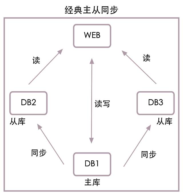
The picture above shows 1 platform web The server and 3 Station database , among DB1 It's the main warehouse ,DB2 and DB3 It's from the library . Let's assume here that web The server is maintained by the project team , The database server consists of DBA maintain .
When from the library DB2 When something goes wrong ,DBA The project team will be notified , The project team will DB2 from web Delete... From the configuration list of the service , restart web The server , This is the wrong node DB2 Will no longer be accessed , The entire database service is restored , etc. DBA Repair DB2 when , Then the project team will DB2 Add to web service .
When the main library DB1 When something goes wrong ,DBA Will DB2 Switch to main library , And inform the project team , The project team uses DB2 Replace the original main library DB1, restart web The server , such web The service will use the new master library DB2, and DB1 Will no longer be accessed , The entire database service is restored , etc. DBA Repair DB1 when , then DB1 As DB2 From the library .
The classical structure above has great disadvantages : No matter what happens to the master or slave database , Need to be DBA Cooperate with the project team to complete database service recovery , It's hard to automate , And the restoration work is too slow .
We think , Database operation and maintenance should be separated from the project team , When there is a problem with the database , Should be DBA Achieve unified recovery , There is no need for the project team to operate services , It's easy to automate , Shorten service recovery time .
Let's first look at the highly available structure of the library :

As shown in the figure above ,web The server will no longer connect directly from the library DB2 and DB3, It's about connecting LVS Load balancing , from LVS Connect from library . The advantage of this is LVS Can automatically sense whether the slave library is available , Slave Library DB2 After downtime ,LVS The read data request will not be sent to DB2. meanwhile DBA When you need to add or remove slave nodes , Just operate independently LVS that will do , There is no longer a need for project groups to update configuration files , Restart the server to cooperate .
Let's look at the high availability structure diagram of the main database :

As shown in the figure above ,web The server will no longer be directly connected to the main library DB1, It's about connecting KeepAlive A virtual thing ip, Make this virtual again ip Map to main library DB1 On , Simultaneous addition DB_bak Slave Library , Real time synchronization DB1 Data in . Under normal circumstances web Still DB1 Read and write data in , When DB1 After downtime , The script will automatically DB_bak Set as main library , And will virtual ip Mapping to DB_bak On ,web The service will use healthy DB_bak Read and write access as the main library . It only takes a few seconds , Can complete the main database service recovery .
Combine the structure above , Get master-slave high availability structure chart :

Database high availability also includes data patching , Because when we operate the core data , All log first and then update , In addition, it realizes the fast recovery of database services in near real time , So the amount of data patched is not large , A simple recovery script can quickly complete data repair .
5、 ... and 、 Data classification
In addition to the most core payment order table and payment flow table in the payment system , There are also some configuration information tables and some user related information tables . If all the read operations are completed on the database , The performance of the system will be greatly reduced , So we introduced the data classification mechanism .
We simply divide the data of payment system into 3 level :
The first 1 level : Order data and payment flow data ; These two pieces of data require high real-time and accuracy , So no cache is added , Read and write operations will directly operate the database .
The first 2 level : User related data ; These data are related to users , It has the characteristics of reading more and writing less , So we use redis Cache .
The first 3 level : Payment configuration information ; It's not about users , Small amount of data , Frequent reading , Features that are barely modified , So we use local memory for caching .
There is a data synchronization problem using the local memory cache , Because the configuration information is cached in memory , And the local memory can't perceive the modification of configuration information in the database , This will cause the data in the database and the data in the local memory is inconsistent .
To solve this problem , We have developed a highly available message push platform , When the configuration information is modified , We can use push platform , Push profile update message to all servers of payment system , The server will automatically update the configuration information after receiving the message , And give success feedback .
6、 ... and 、 Thick and thin pipes
The hacker attacks , Some reasons, such as front-end retry, may cause the request volume to soar , If our service is killed by a surge of requests , Want to restore , It is a very painful and tedious process .
A simple example , Our current order processing capacity is average 10 Ten thousand orders per second , Peak value 14 Ten thousand orders per second , If there is 100 Ten thousand order requests enter the payment system , There is no doubt that our whole payment system will collapse , The continuous requests will make our service cluster unable to start at all , The only way is to cut off all the traffic , Restart the entire cluster , Then slowly import the traffic .
We're outside web Add a layer to the server “ Thick and thin pipes ”, Can solve the above problems very well .
The following is a simple structure diagram of thick and thin pipelines :

Please see the structure diagram above ,http The request is entering web Before cluster , It will pass through a layer of thick and thin pipes first . The entrance end is rough , We set the maximum support 100 Ten thousand requests per second , Redundant requests will be discarded directly . The exit end is a slit , We set it up for web colony 10 Ten thousand requests per second . remainder 90 Ten thousand requests will be queued in thick and thin pipes , wait for web After the cluster has processed the old request , There will be new requests coming out of the pipeline , to web Cluster processing . such web The number of requests processed by the cluster per second will never exceed 10 ten thousand , Under this load , All services in the cluster will run in Colleges and universities , The whole cluster will not stop service due to the increasing requests .
How to realize thick and thin pipes ?nginx Support already exists in the Business Edition , Please search for relevant information
nginx max_conns, It should be noted that max_conns Is the number of active connections , In addition to the specific settings need to determine the maximum TPS Outside , It is also necessary to determine the average response time .
边栏推荐
- 【游标的嵌套】mysql存储过程游标的嵌套
- vs2017 在调试状态不显示QString值的解决方法
- 浙江创投圈的“半壁江山”,还得是国资
- 代码扫描工具扫出的 Arrays.asList 使用BUG
- [MYSQL]数据同步提示:Specified key was too long;max key length is 767 bytes
- ERROR 1364 (HY000): Field ssl_cipher doesnt have a default value
- 执行逻辑大同小异的实现类使用模板模式
- [C language] deeply analyze the storage of integer and floating-point types in memory
- 交互电子白板有哪些特点?电子白板功能介绍
- variable
猜你喜欢

VHEDT业务发展框架

买网红雪糕的我,成了大冤种
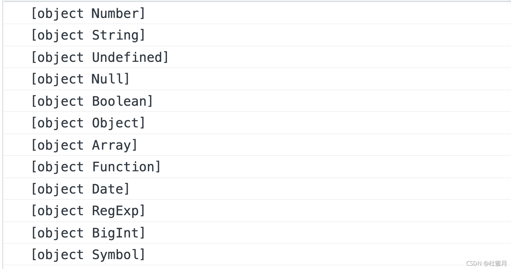
Summary of JS methods for obtaining data types

Machine learning notes - Hagrid - Introduction to gesture recognition image data set
![[pop up box at the bottom of wechat applet package] I](/img/28/7cb36ef4fcf753764cc9363a323a20.png)
[pop up box at the bottom of wechat applet package] I
![[wechat applet custom bottom tabbar]](/img/04/2ea4ab3fd8571499190a9b3c9990b2.png)
[wechat applet custom bottom tabbar]

Lecture 6 of slam Lecture 14 -- nonlinear optimization
![[pop up box 2 at the bottom of wechat applet package]](/img/31/266e6a1f4200347c9324ea37b78562.png)
[pop up box 2 at the bottom of wechat applet package]
![[C language] deeply analyze the storage of integer and floating-point types in memory](/img/8b/12a4dc7a0c0e34e2add007592971dd.jpg)
[C language] deeply analyze the storage of integer and floating-point types in memory

What is SAP ABAP? Type, ABAP full form and meaning
随机推荐
Test for API
二叉树练习第二弹
In case of default import failure
jsp学习之(一)---------jsp概述
for.. of vs. for.. In statement
联合主键引发的思考
Oracle database and table
Vhedt business development framework
[wechat applet to obtain the height of custom tabbar] is absolutely available!!!
[C language] deeply analyze the relationship between pointer and array
win10的wifi断线后无法连接
【小程序项目开发-- 京东商城】uni-app开发之轮播图
SAP ABAP internal tables: create, read, populate, copy and delete-06
Test for API
JSP learning (2) -- JSP script elements and instructions
IDEA安装总结
nio服务多线程版本
SAP ABAP sub screen tutorial: call sub screen -010 in SAP
[pop up box 2 at the bottom of wechat applet package]
spark的NaiveBayes中文文本分类