当前位置:网站首页>Discrete device ~ diode triode
Discrete device ~ diode triode
2022-06-26 08:15:00 【circuit in my brain】
One 、 diode
1、 Basic knowledge points
take p Type a semiconductors and N Type semiconductors combine at the atomic level to form PN junction , As shown in the figure below , Because the contact electric field exists in PN A fixed voltage drop is formed on the junction , Silicon materials are generally 0.6v, Germanium materials are generally 0.3~0.5v, Germanium material has strong temperature sensitivity , The stability is not as good as that of silicon .

PN The volt ampere characteristic curve of the junction is shown in the figure below ,V2 Is the voltage of forward conduction ,V1 Is the reverse breakdown voltage ;
V1 The voltage at point is relatively stable ( After limiting the current, the voltage can be stabilized ), The voltage at this point can be made into different values through different processes .
V2 The voltage at point is not stable , The tube voltage drop is different under different current conditions , So when we use a multimeter to measure the tube voltage drop, it may be different from the actual use in the circuit .

2、 Different types of diodes
1> Small signal switching diode
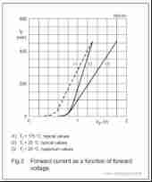
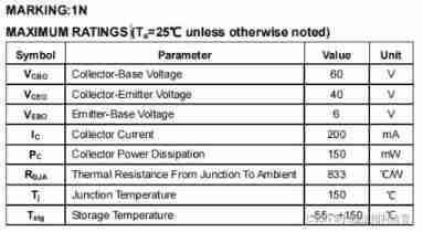
With the most commonly used 1N4148 For example , The parameters are as follows :

The volt ampere characteristic curve is shown in the figure below :
2> Schottky diode


Compare Schottky and small signal switch , Each has its own characteristics , The bulk capacitance of the small signal switch is relatively small , The leakage current is also very small , Schottky leakage current is generally large , The bulk capacitance is also very large .
Two 、 triode
1、 The main function of triode is to amplify the current , The schematic diagram is as follows ,

When the emission junction is satisfied BE Positive deviation , Collector BC When the reverse bias , The emitter junction will have a current flowing from the base to the emitter Ib, At the same time, the collector junction is turned on in reverse , Form collector current , Flow through the base to the emitter , The emitter current is the base current plus the collector current , There are the following relationships :

2、BJT Input and output characteristics of
1> Input characteristic curve

Be careful. : When Uce>1v when , The characteristic curve moves to the right !Ube The value of has increased .

The output characteristic in the figure above is the output curve of the common emission amplifier circuit , As can be seen from the above figure :
1> Cut off zone : With Ib Reduce to a certain value , No matter how much Uce,Ic The current is maintained at a small value .
2> Zoom in : Zoom in on the middle of the curve , Collector current Ic=β*Ib.
3> Saturation zone : stay Uce At the beginning, it gradually increases ,Ic Gradually increasing current , Is an approximately linear increase . Generally, when entering the saturation zone , Transistor's ce The pressure drop is 0.3v about .
3、 Bandwidth of triode
The bandwidth of the common emitter amplifier circuit is the same as that of the common base amplifier circuit
The bandwidth of the three kinds of amplifier circuits is the narrowest , The frequency characteristic is the worst , Not suitable for amplifying high frequency signals . The cause of this problem is shown in the figure below :
1> resistance r And Cbe Constitute a low-pass filter , Unavoidable and not magnified .
2> resistance r And Cbc Constitute a low-pass filter , However, the connection method of common emission amplifier circuit has the effect of multiplication and low-pass .

Common base amplifier circuit because the input is in E extremely , Output in C extremely , Because of IE≈IC, So there is no current amplification capability , Only voltage amplification capability , That is, it has the characteristics of current following ; Low input resistance , Voltage amplification 、 The output resistance is equivalent to that of a common emitter circuit , Good high frequency characteristics ; Input and output are in phase , In phase amplification .

Input capacitance and capacitance of common base amplifier circuit RE There is no low-pass filter , To verify this problem , I did a simulation .
1> An emitter resistor is added after the emitter resistor 10u capacitance ,R4 And R3 Constitute a low-pass filter , The cut-off frequency is 16Hz, Then the amplitude of the input signal will be sufficiently attenuated , Then the amplitude of my output signal must be very small , But the green waveform below is the output waveform .

after R4 And R3 It is indeed attenuated enough .

3、 Parameters of triode
MMBT3904 Parameters of , Commonly used Ic Size , On the switch parameter ft, The switch speed should be fast enough , There are few triodes with large current , The models that can be found if these two conditions are met are MMBT3904 + MMBT3906( Two pairs of tubes ) MMBT2222A + MMBT2907( Two pairs of tubes )

边栏推荐
- Win11 open folder Caton solution summary
- Project practice: parameters of pycharm configuration for credit card digital recognition and how to use opencv in Anaconda
- Wechat applet beginner level chapter
- Interview JS and browser
- 1GHz active probe DIY
- Opencv鼠标事件+界面交互之绘制矩形多边形选取感兴趣区域ROI
- Bluebridge cup 1 introduction training Fibonacci series
- Google Earth engine (GEE) 02 basic knowledge and learning resources
- Opencv mouse event + interface interaction drawing rectangle polygon selection ROI
- MySQL practice: 1 Common database commands
猜你喜欢

Database learning notes II

Automatic backup of MySQL database in the early morning with Linux

Interview for postgraduate entrance examination of Baoyan University - machine learning

Cause analysis of serial communication overshoot and method of termination

(vs2019 MFC connects to MySQL) make a simple login interface (detailed)

MySQL practice: 2 Table definition and SQL classification

Chapter 4 (functions and preprocessing)

Uni app installation and project directory (hbuilder configuration)

JS Date object

X-VLM多模态模型解读
随机推荐
Informatics Olympiad 1355: string matching problem (STRs)
Chapter 9 (using classes and objects)
"System error 5 occurred when win10 started mysql. Access denied"
drf的相关知识
[postgraduate entrance examination] group planning: interrupted
Project practice: parameters of pycharm configuration for credit card digital recognition and how to use opencv in Anaconda
How to debug plug-ins using vs Code
Example of offset voltage of operational amplifier
你为什么会浮躁
Junit
Data governance: from top project to data culture!
Pic 10B parsing
Vs2019-mfc setting edit control and static text font size
Common uniapp configurations
Chapter II (summary)
Listview control
Interview JS and browser
Go language shallow copy and deep copy
Google Earth engine (GEE) 01- the prompt shortcut ctrl+space cannot be used
ASP. Net and Net framework and C #