当前位置:网站首页>Cause analysis of serial communication overshoot and method of termination
Cause analysis of serial communication overshoot and method of termination
2022-06-26 08:12:00 【circuit in my brain】
First of all, let's take a look at our commonly used serial communication wiring methods ,MCU Of RX,TX Let's add one here 33~100Ω To match the impedance of the transmission line ,USB turn TTL This end is not terminated with any resistance ,MCU Here and USB turn TTL This is through 15cm Long DuPont line connection , The circuit diagram is as follows ,USB turn TTL Connected to the upper computer ,MCU adopt TXD Continuously send data to the upper computer ,RXD For the upper computer MCU Send measurement instructions .

1、MCU_TX wave form

2、USB_RX

3、MCU_RX

4、USB_TX
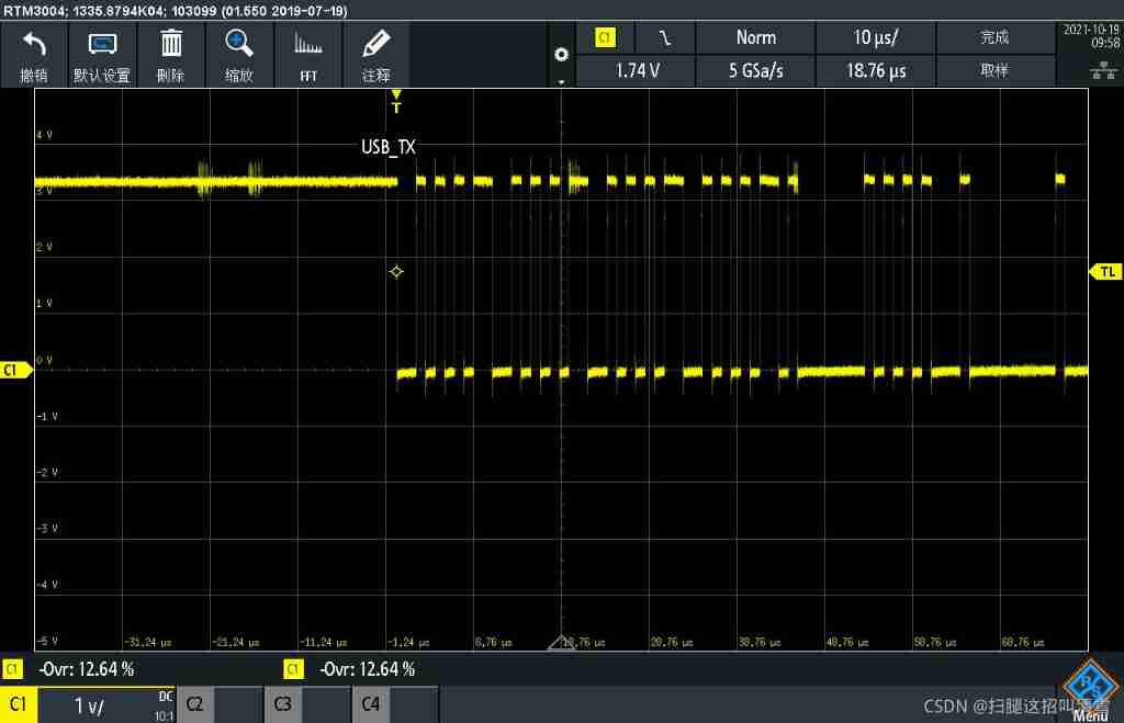
We have found the problem from the above test waveform ,MCU Of TX and USB Of TX There is basically no overshoot ,MCU Of RX and USB Of RX All have relatively large overshoot , This overshoot one 15% One 30%, Overshoot is relatively large , The cause of this overshoot is the impedance mismatch , And the long wire makes us see the reflection of the signal .
We use MCU_TX( Proximal end ) and USB_RX( Distal ) Take this group for example , We put the matching 100R Remove the resistor , Look at the waveform of the remote end as follows :

It can be found that the overshoot increases again 3% about .
And then we put 100R Resistance welding back , Parallel one at the far end 470p capacitance , This increases the transmission delay , Let us ring and drown in the rising edge , So we can see the waveform at the far end without overshoot .

Some people may say that the communication signal frequency of the serial port is not high , For example, the baud rate of the serial port above me is :961200bps, Look at the frequency 500k When , If the 500k It is far from the frequency that requires impedance matching .
My understanding of this question is as follows :
because commonly No To be terminated Maximum length in Count Is the rising edge of the signal ns Count , That is to say
Len max > RT
Len max Is the maximum length of a transmission line that is not terminated ,RT Is the rising edge of the signal . for instance : The signal 10M The frequency of , The clock period is 100ns, The rising edge is 10ns, Then the maximum length of the transmission line that does not need to be terminated is 10in, Test us MCU Of TX The rising edge time of is shown in the figure below , It can be seen that the rise time is 1.1ns, That is, the maximum length of the transmission line that does not need to be terminated 1.1in, That is to say 2.79cm, The length of the transmission line we use is 15cm about , So we can see the reflection of the signal . We solved the problem of reflection by adding a capacitor at the far end , Is to make the rising time of the signal longer , Submerge the reflection in the rising edge process .

边栏推荐
- Opencv mouse event + interface interaction drawing rectangle polygon selection ROI
- Google Earth engine (GEE) 02 basic knowledge and learning resources
- h5 localStorage
- Go语言浅拷贝与深拷贝
- buuresevewp
- 信息学奥赛一本通 1354:括弧匹配检验
- I want to create SQL data (storage structure)
- 4 best practices for wireless (OTA) updates
- 解决 psycopg2.NotSupportedError: PQconninfo not available in libpq < 9.3
- What are the key points of turnover box management in warehouse management
猜你喜欢

Detailed explanation of the generate go file command of import in golang (absolute detail)

Rewrite string() method in go language

Idea auto Guide

Seven important reasons for responsive Web Design

Wechat applet beginner level chapter

MySQL query time period

Chapter VII (structure)

How to define a digital factory and what is the relationship with smart factory and industry 4.0

Crawler case 1: JS reversely obtains HD Wallpapers of minimalist Wallpapers

Oracle 19C download installation steps
随机推荐
记一次开发 pgadmin 时执行 Building the Web Assets 遇到的依赖安装问题
Blue Bridge Cup 3 sequence summation
Oracle 19C local listener configuration error - no listener
Golang collaboration and channel usage
Real machine debugging of uniapp custom base
Baoyan postgraduate entrance examination interview - operating system
Use intent to shuttle between activities -- use explicit intent
PCB miscellaneous mail
The 9th zero code training camp is officially open for registration! (Beijing, Shanghai, Guangzhou and Shenzhen)
Basic use of swiperefreshlayout, local refresh of flutterprovider
Data governance: from top project to data culture!
Software engineering - high cohesion and low coupling
Livevideostackcon | evolution of streaming media distribution for online education business
See which processes occupy specific ports and shut down
Idea automatically sets author information and date
StarWar armor combined with scanning target location
Uniapp uses uviewui
MySQL practice: 3 Table operation
I want to open a stock account at a discount. How do I do it? Is it safe to open a mobile account?
How to define a digital factory and what is the relationship with smart factory and industry 4.0