当前位置:网站首页>Temperature, humidity and light intensity acquisition based on smart cloud platform
Temperature, humidity and light intensity acquisition based on smart cloud platform
2022-07-25 09:52:00 【F l e】
This design adopts esp8266 Burn smart cloud firmware .esp8266 And stm32 communicate , be stm32 Can pass esp8266 Data interaction with smart ECS , And the smart cloud server can work with the smart cloud app Data interaction , therefore stm32 adopt esp8266 Can work with smart cloud app Data interaction .stm32 As MCU Data interaction with sensors , Get the value collected by the sensor , So the sensors and app Data interaction . Because this experiment increases the acquisition of light intensity , So a tricolor is added RGB Lamp peripherals . Through Jizhi cloud app Can be adjusted RGB Light intensity of lamp , To simulate the change of light intensity . The sensor data flow of the whole design is shown in the figure below :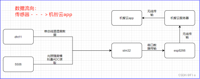
in addition , For using smart cloud app Adjust the RGB The data flow of light intensity is shown in the figure below :
One 、 Sensor testing
This design uses STM32CubeMX Development , The code design process is divided into modules , Write test cases to verify the functions of each module , Include oled modular 、 Key module 、dht11 modular 、 Photoresistor module 、rgb modular .
1、oled modular
① connection :
| Stm32 | oled |
|---|---|
| 3.3V | VCC |
| GND | GND |
| PB13 | D0 |
| PB15 | D1 |
| PB4 | RES |
| PB3 | DC |
| GND | CS |
② Code writing :
In this design oled Using hardware SPI2 drive ,STM32CubeMX The design of is shown in the figure below :


utilize STM32CubeMX Generated SPI The main code is shown above . In the generated SPI Write further on the code oled.c and oled.h file .
oled.c The following functions are encapsulated :
Test functions :
int main(void)
{

    HAL_Init();
    SystemClock_Config();
    MX_GPIO_Init();
    MX_SPI2_Init();
    OLED_Init();
    OLED_ShowString(0, 0, "wait for set esp8266,press key1 to set esp8266 with AIRLINK_MODE");
}
③ Test case experimental results :
It can be seen from the above figure ,oled The display function of the module can correctly display .
2、 Key module
① connection :
KEY_R0 Grounding ,KEY_L0 and KEY_L1 It can be used to detect the key state .
The corresponding pin is :
| KEY_R0 | PC11( Low level output by MCU ) |
|---|---|
| KEY_L0 | PC10 |
| KEY_L1 | PB5 |
② Code writing :
STM32CubeMX The design is as follows :
PC11 Set to output mode ,PC10 and PB5 Set to input mode .
Key.c The following functions are encapsulated :
void key_init(void)
{

   HAL_GPIO_WritePin(KEY_COM_GND_GPIO_Port, KEY_COM_GND_Pin, GPIO_PIN_RESET);
}

void Test_key(void)
{

   if(HAL_GPIO_ReadPin(KEY1_GPIO_Port, KEY1_Pin)==GPIO_PIN_SET)
   {

      OLED_ShowString(0,0,"key1_up");
   }
   else
   {

      OLED_ShowString(0,0,"key1_down");
   }
   if(HAL_GPIO_ReadPin(KEY2_GPIO_Port, KEY2_Pin)==GPIO_PIN_SET)
   {

      OLED_ShowString(0,10,"key2_up");
   }
   else
   {

      OLED_ShowString(0,10,"key2_down");
   }
   OLED_Refresh_Gram();
}
The test case :
int main(void)
{

   MX_GPIO_Init();
   key_init();
   while(1)
   {

      Test_key();
   }
}
③ Test case experimental results :
As can be seen from the picture , As soon as the key is pressed key1_down and key2_up, Consistent with the theory .
3、dht11 modular
① connection :
| Stm32 | Dht11 |
|---|---|
| 3.3V | VCC |
| GND | GND |
| PB0 | DAT |
② Code writing :
because dht11 The data pin of sometimes needs to be used as input , Sometimes it needs to be used as output , So it's not STM32CubeMX Set up .
Dht11.c It mainly encapsulates the following functions :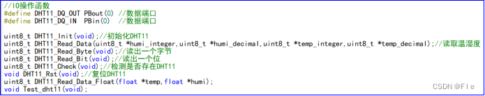
there us The time delay is not generated by using a timer , It is realized by system clock :
void delay_us(uint32_t us)
{

    uint32_t delay = (HAL_RCC_GetHCLKFreq() / 4000000 * us);
    while (delay--)
   {

      ;
   }
}
The test case :
int main(void)
{

  HAL_Init();
  SystemClock_Config();
  MX_GPIO_Init();
  MX_SPI2_Init();
  OLED_Init();
  while(1)
  {

      Test_dht11();
   }

void Test_dht11(void)
{

   char txt[16];
   while(1)
   {

      DHT11_Read_Data(&humidity_integer,&humidity_decimal,&temperature_integer,&temperature_decimal);
      sprintf(txt, "temp:%d.%d", temperature_integer,temperature_decimal);
      OLED_ShowString(0,0,txt);
      sprintf(txt, "humi:%d.%d", humidity_integer,humidity_decimal);
      OLED_ShowString(0,10,txt);
      OLED_Refresh_Gram();
   }
}
③ Test case experimental results :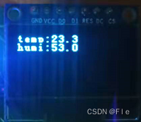
As can be seen from the figure above , The temperature is 23.3℃, The humidity is 53.0%, The decimal of humidity is 0, Consistent with the theory .
4、 Photoresistor module
① connection :
| Stm32 | 5506 |
|---|---|
| 3.3V | VCC |
| GND | GND |
| PA0 | AO |
② Code writing :
STM32CubeMX Set up ADC1 Of IN0 as follows :
Stm32Rct6 Of ADC yes 12 Bit , There are no options to change , be ADC The maximum value read is 2^12=4096.
Here is the sampling time Sampling Time choice 1.5 A cycle .ADC Sampling time = ( Sampling period +12.5 cycle )* 1/ADC clock frequency , here ADC Sampling time =(1.5+12.5)*1/12 = 1.167us.
light_check5506.c It mainly encapsulates the following functions :
void light_check5506_init(void)
{

   HAL_ADCEx_Calibration_Start(&hadc1);
   HAL_Delay(200);
}

uint32_t light_check5506_getinitvalue(void)
{

   HAL_ADC_Start(&hadc1);
  HAL_ADC_PollForConversion(&hadc1,50);//ÏÞʱ50ms
   return HAL_ADC_GetValue(&hadc1);
}

uint32_t light_check5506_get0to100value(void)
{

   //°µ-->ÁÁ£º0~100
   uint32_t value;
   value=light_check5506_getinitvalue();
   value=4096-value;//ÔʼÊý¾ÝÊÇÔ½°µÊý¾ÝÔ½´ó
   value=(value*100/4096);//»¯Îª0~100µÄÊý,±ØÐëÏȳËÒÔ100ÔÙ³ý£¬ÒòΪȫ²¿ÊÇÕûÊý
   return value;
}

void Test_5506(void)
{

   uint32_t value;
   char txt[16];
   while(1)
   {

      value=light_check5506_get0to100value();
      sprintf(txt, "light(0-100):%d", value);
      OLED_ShowString(0,0,txt);
      OLED_Refresh_Gram();
   }
}
The test case :
main(void)
{

    HAL_Init();
    SystemClock_Config();
    MX_GPIO_Init();
    MX_SPI2_Init();
    MX_ADC1_Init();
    OLED_Init();
    light_check5506_init();
    while(1)`
    {

        Test_5506();
    }
}
③ Test case experimental results :
take ADC The read value is normalized to 0~100 The value of rear illumination intensity is 18.
5、rgb modular
① connection :
| Stm32 | rgb |
|---|---|
| GND | GND |
| PC6 | R |
| PC7 | G |
| PC8 | B |
② Code writing :
STM32CubeMX Set up TIM8 The three channels of are as follows :
Count period Counter Period Set to 255, This is for the convenience of searching RGB Color table for color settings , Duty cycle Pulse Set to 50%
Rgb.c The following functions are encapsulated :
void rgb_init(void)
{

   HAL_TIM_PWM_Start(&htim8,TIM_CHANNEL_1);
   HAL_TIM_PWM_Start(&htim8,TIM_CHANNEL_2);
   HAL_TIM_PWM_Start(&htim8,TIM_CHANNEL_3);
}
void Test_rgb(void)
{

    rgb_setpwm(10.0,100.0,200.0);
}
void rgb_setpwm(uint8_t pwm_r,uint8_t pwm_g,uint8_t pwm_b)
{

   __HAL_TIM_SET_COMPARE(&htim8, TIM_CHANNEL_1,pwm_r);
   __HAL_TIM_SET_COMPARE(&htim8, TIM_CHANNEL_2,pwm_g);
   __HAL_TIM_SET_COMPARE(&htim8, TIM_CHANNEL_3,pwm_b);

}
The test case :
main(void)
{

    HAL_Init();
    SystemClock_Config();
    MX_GPIO_Init();
    MX_SPI2_Init();
    MX_TIM8_Init();
    rgb_init();
    OLED_Init();
    while(1)`
    {

       Test_rgb();
}
}
③ Test case experimental results :
It can be seen from the above figure RGB The light is on .
Two 、 adopt esp8266 Realize data upload and data return
Before data upload and data return , First, the serial port for printing data 1 Settings and for stm32 And esp8266 Serial port for communication 2.
A serial port 1:
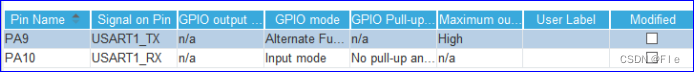
A serial port 1 Set up PA9 and PA10 Respectively as TX and RX, The baud rate is 115200, Do not enable interruptions .
A serial port 2:


A serial port 2 Set up PA2 and PA3 Respectively as TX and RX, The baud rate is 9600, To interrupt .
( One ) Data upload ------ Temperature and humidity data 、 Care intensity data
① Main code
void userHandle(void)
{

    DHT11_Read_Data( & humidity_integer, & humidity_decimal, & temperature_integer, & temperature_decimal);
    currentDataPoint.valuehumidity = humidity_integer;
    currentDataPoint.valueLight_intensity = light_check5506_get0to100value();
    currentDataPoint.valueDHT11 = temperature_integer + 0.1 * temperature_decimal;
}
stay userHandle(void) Add temperature and humidity data acquisition and light intensity reading .userHandle() yes main Function while The contents of the cycle .
As can be seen from the left figure ,userHandle It is the top level for users , The data is in userHandle Middle acquisition , Pass by in turn gizCheckReport Judge whether to report the data of current status 、gizDataPoints2ReportData Complete the conversion from user area data to reporting data 、gizReportData Send the converted report data to WiFi modular .
② Design results :
First, make sure esp8266 And mobile phones have been connected to the same network , Here, computers are used as this network .
It can be seen from the above figure that mobile phones and esp8266 The computer has been connected . Wit cloud app Connected to the esp8266 Get the uploaded data :

Oled The data on stm32 Collected , The data in the figure on the right is app adopt esp8266 received , The two are the same , It shows that the data interaction is correct .
( Two ) Data back ------RGB Three values
① Main code
int8_t gizwitsEventProcess(eventInfo_t * info, uint8_t * gizdata, uint32_t len)
{

    uint8_t i = 0;
    dataPoint_t * dataPointPtr = (dataPoint_t *)gizdata;
    moduleStatusInfo_t * wifiData = (moduleStatusInfo_t *)gizdata;
    protocolTime_t * ptime = (protocolTime_t *) gizdata;
    # if MODULE_TYPE
    gprsInfo_t * gprsInfoData = (gprsInfo_t *)gizdata;
    # else
    moduleInfo_t * ptModuleInfo = (moduleInfo_t *) gizdata;
    # endif
    if ((NULL == info) || (NULL == gizdata))
    {

        return -1;
    }
    for (i=0; i < info->num; i++)
    {

        switch(info->event[i])
        {

            case EVENT_LED_R:
                currentDataPoint.valueLED_R = dataPointPtr->valueLED_R;
                GIZWITS_LOG("Evt:EVENT_LED_R %d\n", currentDataPoint.valueLED_R);
                rgb_setpwm(currentDataPoint.valueLED_R, currentDataPoint.valueLED_G, currentDataPoint.valueLED_B);
                break;
            case EVENT_LED_G:
                currentDataPoint.valueLED_G = dataPointPtr->valueLED_G;
                GIZWITS_LOG("Evt:EVENT_LED_G %d\n", currentDataPoint.valueLED_G);
                rgb_setpwm(currentDataPoint.valueLED_R, currentDataPoint.valueLED_G, currentDataPoint.valueLED_B);
                break;
            case EVENT_LED_B:
                currentDataPoint.valueLED_B = dataPointPtr->valueLED_B;
                GIZWITS_LOG("Evt:EVENT_LED_B %d\n", currentDataPoint.valueLED_B);
                rgb_setpwm(currentDataPoint.valueLED_R, currentDataPoint.valueLED_G, currentDataPoint.valueLED_B);
                break;
        }
    }
}
stay gizwitsEventProcess Medium EVENT_LED_R、EVENT_LED_G、EVENT_LED_B Add pairs respectively RGB Three PWM Assignment , Make it effective immediately after assignment .
protocolIssuedProcess By gizwitsHandle call , Receive from the cloud or app Relevant protocol data sent by the client .ACTION_CONTROL_DEVICE Conduct “ Control Protocol ” Related treatment ,gizDataPoint2Event Generate according to the agreement “ Controlled event ”, And transform the corresponding data types ,gizwitsEventProcess It is located at the bottom of the data return process , According to the generated “ Controlled event ” Deal with it accordingly .
② Design results :
First, make sure esp8266 And mobile phones have been connected to the same network , Here, computers are used as this network .
It can be seen from the above figure that mobile phones and esp8266 The computer has been connected . Wit cloud app Set up RGB Three PWM The number , obtain oled The data on is :
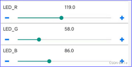
It can be seen from the above figure , The right to app Set three PWM The number , Left figure again oled The above is the same value , It indicates that the data interaction is correct .
3、 ... and 、 Summary and experience
① Through this design contact STM32CubeMX This software , Compared with the previous standard library ,STM32CubeMX Generated Hal The library is not only more encapsulated , And it is more conducive to developers' rapid development , And the code generated by the smart cloud in this experiment is also based on Hal Library , This shows that for stm32 Come on , Will tend to Hal Development .
② The official website is always the best place to solve problems , The official documents of smart cloud have greatly helped me .
③esp8266 The burning of is very demanding for power supply , Many times of burning failed , So I'm making pcb I added esp8266 Burning interface , as well as GPIO Grounding switch of , There is also a reset circuit .
④stmRct6 The power supply of the board is very poor , Because I just took it at first ST-LINK Power supply , Lead to dht11 and oled When used together dht11 Of VCC Only mouth 2.6V, Thus making dht11 Communication has been unsuccessful , This also shows that everything starts with power management , Make sure the power supply is OK, and then find the software problem .
appendix
1、PCB Expansion board 
PCB Project links :
link :https://pan.baidu.com/s/1mASqMcT1FdAu_I2DBkxMeg
Extraction code :xydq
2、 Code
link :https://pan.baidu.com/s/1fQRfchWXtGXmWRjT9O1fTw
Extraction code :jaam
边栏推荐
猜你喜欢


随机推荐
*7-1 CCF 2015-09-1 sequence segmentation
Raspberry sect door ban system based on face recognition
深度估计自监督模型monodepth2在自己数据集的实战——单卡/多卡训练、推理、Onnx转换和量化指标评估
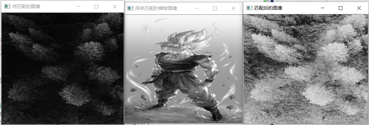
First knowledge of opencv4.x --- image template matching
Use kotlin use to simplify file reading and writing
一个硬件攻城狮的经济学基础
[data mining] nearest neighbor and Bayesian classifier
Introducing MLOps 解读(一)
低功耗和UPF介绍
【Tensorflow2安装】Tensorflow2.3-CPU安装避坑指南!!!
CCF 201604-2 俄罗斯方块
chmod和chown对挂载的分区的文件失效
Customize dialog to realize the pop-up box of privacy clause statement imitating Netease cloud music
Kotlin basic knowledge points
Segmentation based deep learning approach for surface defect detection
[deep learning] self encoder
Some skills to reduce the complexity of program space
Save pdf2image PDF file as JPG nodejs implementation
解决esp8266无法连接手机和电脑热点的问题
【数据挖掘】最近邻和贝叶斯分类器