当前位置:网站首页>Camera attitude estimation
Camera attitude estimation
2022-07-25 09:51:00 【F l e】
One 、 Camera attitude estimation principle

First of all, let's introduce what is the world coordinate system and camera coordinate system —— The world coordinate system is a coordinate system defined by oneself , Here I define the world coordinate system as X Axis vertical screen points to people ,Y The axis is horizontal to the right ,Z The shaft is vertically upward . There are unified provisions for the camera coordinate system , As shown in the figure ,x The axis is parallel to the camera lens to the left ,y The axis is parallel to the camera lens down ,z The axis is perpendicular to the lens and points horizontally at the person .
Our need to find the pose of the camera in the world coordinate system is often to find the coordinates of a point in the camera coordinate system in the world coordinate system , Or the coordinates of a point in the world coordinate system in the camera coordinate system .
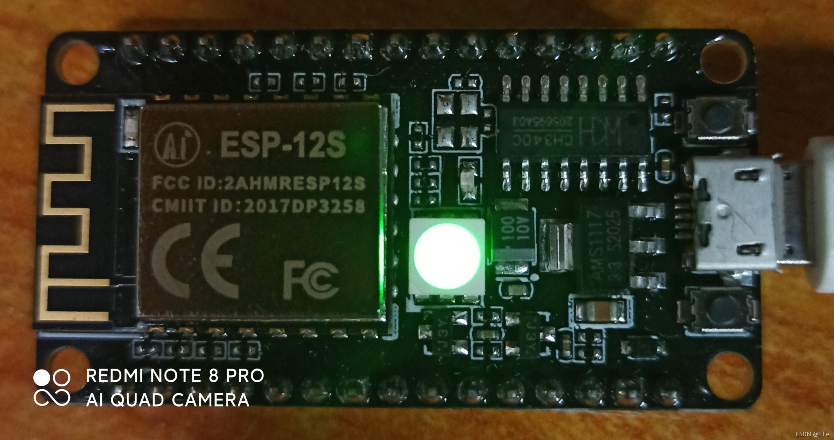
First, think about why you can determine the attitude of the camera in a certain world coordinate system ( Posture refers to the specific position of the camera in the world coordinate system , Include xyz Rotation and translation of coordinate axis ). If the camera coordinate system is relatively static with the world coordinate system , Then the relationship between the two is certain , Through certain methods, we can certainly calculate the relationship between the two . Someone must ask here how many cameras are needed to calculate the relationship between the two , The answer is just one ( The above schematic picture is just because I don't have a monocular camera , Only the left camera was used in the whole experiment ). The premise of using only one camera is to know the internal parameters of the camera , Including internal parameter matrix and distortion matrix . As for why we can use a camera to calculate the attitude of the camera when we know the internal parameter matrix and distortion matrix, we haven't fully understood it yet .

In the diagram above , Lowercase xyz Is the coordinate of the point in the camera coordinate system , uppercase XYZ Is the coordinate of the point in the world coordinate system .R33 It's a rotation matrix ,T31 It's a translation matrix , What is worth noting here is , The units of coordinates should be unified , The second is When the entered world coordinate is the actual coordinate value , The calculated translation matrix is also the actual translation amount . Our goal is to find the rotation matrix and the translation matrix .
Now let's introduce these two matrices :
① Rotation matrix :
Now ask A To B The rotation matrix of ,XB、YB、ZB、XA、YA、ZA It refers to the unit vector in the direction of each coordinate axis .A Is the world coordinate system ,B Is the camera coordinate system .

Then there are 
Know the meaning of the items of the rotation matrix , It can help us roughly judge whether the rotation matrix we calculate is correct .
② Translation matrix
Now go back to this picture :
If a point is required, the coordinate of the point in the world coordinate system is in the camera coordinate system , The coordinates of the point in the world coordinate system are [X;Y;Z] ( Here we use 31 The matrix of represents points ), Then after finding the rotation matrix , from R[X;Y;Z] The coordinates of the point in the rotated world coordinate system can be obtained , At this time, the world coordinate system becomes a coordinate system with three coordinate axes parallel to the three coordinate axes of the camera coordinate system , As shown in the figure below :
And one of the ▲x,▲y They are the distance between the corresponding axes of the two coordinate systems in the above figure (z It's the same with the shaft , If it's a little difficult to draw, don't draw ). Translation matrix T=[▲x;▲y;▲z]. Through geometric meaning, we can also roughly judge whether the calculated translation matrix is correct .
Two 、 Camera attitude estimation implementation
First, we need to get the internal parameters of the camera , The camera's internal parameter matrix and distortion matrix can be obtained by Zhang Zhengyou's calibration method . The specific steps will not be carried out here , The following is my internal parameter matrix and distortion matrix :
The resolution of the camera is 19201080, The pixel size of the camera is 2.2um2.2um.
The rotation matrix and translation matrix are obtained through Opencv Of PnP Algorithm , The function used is solvePnP, Let's introduce this function :


Functions can be introduced in here find
We can know from the function introduction above , What we need to do is to achieve at least 4 Right match point , That is, the two-dimensional coordinate points of the image and the three-dimensional coordinate points in the world coordinate system . How to get the coordinates of the point in the world coordinate system more accurately requires us to think carefully . Because my world coordinate system here is quite special , I used a carbon rod , Mark a small white dot on the carbon rod , Let the flat section of the carbon rod be perpendicular to the screen and close to , The world coordinates of the next point on the screen can be obtained by manual measurement , And the little white one X The coordinate is the distance from the carbon rod to the small white spot ,YZ The coordinate value is the same as the adjacent point .
From the beginning of the article to now, we are all seeking the rotation matrix and translation matrix from the point of the world coordinate system to the point of the camera coordinate system , Then if the rotation matrix and translation matrix from the point of the camera coordinate system to the point of the world coordinate system are required , Then we can first find the rotation matrix from the point in the world coordinate system to the point in the camera coordinate system R Peaceshift matrix T, Then the coordinates of the points in the camera coordinate system in the world coordinate system are obtained through the following formula :
The implementation code is as follows :
My goal here is to find the world coordinates of the optical centers of the two cameras .
#include <opencv2\opencv.hpp>
#include <fstream>
#include <iostream>
#include <vector>
#include <Eigen/Core>
#include <Eigen/SVD>
#include <Eigen/Dense>
#include <Eigen/Geometry>
#include <cmath>
using namespace std;
using namespace cv;
using namespace Eigen;

int main()
{

	Mat rvec_L, tvec_L, rvec_R, tvec_R;
	// The internal parameter matrix of the left camera
	Mat cameraMatrix_L = (Mat_<double>(3, 3) << 1492.320675688276, 0, 1042.383048569903,
											   0, 1443.277689279584, 561.8151909811569,
											   0, 0, 1);
	// Distortion matrix of left camera
	Mat disCoeffs_L = (Mat_<double>(1,5) << 0.8855691467581785, -3.76931898492866, 0.001722608150198718, 0.09559525553142016, 8.767109962143531);
	// The internal parameter matrix of the right camera
	Mat cameraMatrix_R = (Mat_<double>(3, 3) << 1489.387347765696, 0, 1155.32002834218,
												0, 1446.451497184327, 499.0095775742494,
												0, 0, 1);
	// Distortion matrix of the right camera
	Mat disCoeffs_R = (Mat_<double>(1, 5) << 1.010043485302243, -8.566544837424154, -0.002706277601760965, 0.09466761963281151, 32.5513838899965);
	// Coordinates of matching points , Here take 5 Yes , Don't take it 6 Yes
	vector<Point3d> PointSets = {
     Point3d(415,115,195),Point3d(415,230,195),Point3d(415,345,195),Point3d(415,115,130),Point3d(415,230,130) };
	vector<Point2f> imgPoints_L = {
     Point2f(1230,659),Point2f(841,662) ,Point2f(436,683) ,Point2f(1266,893) ,Point2f(824,864) };
    vector<Point2f> imgPoints_R = {
     Point2f(1428,604),Point2f(1039,607) ,Point2f(640,627) ,Point2f(1483,838) ,Point2f(1040,808) };
	solvePnP(PointSets, imgPoints_L, cameraMatrix_L, disCoeffs_L, rvec_L, tvec_L);
	solvePnP(PointSets, imgPoints_R, cameraMatrix_R, disCoeffs_R, rvec_R, tvec_R);
	Mat R_L, R_R;
	// Convert to rotation matrix , But the format is still Mat type
	Rodrigues(rvec_L, R_L);
	Rodrigues(rvec_R, R_R);
	Matrix<double, 3, 3> Matrix_R_L;// Rotation matrix from world coordinate system to left camera coordinate system
	Matrix<double, 3, 3> Matrix_R_R;// Rotation matrix from world coordinate system to right camera coordinate system
	Matrix<double, 3, 1> Matrix_T_L;// Translation matrix from world coordinate system to left camera coordinate system
	Matrix<double, 3, 1> Matrix_T_R;// Translation matrix from world coordinate system to right camera coordinate system
	Matrix<double, 3, 1> oL_in_world;// The coordinates of the optical center of the left camera in the world coordinate system
	Matrix<double, 3, 1> oR_in_world;// The coordinates of the optical center of the right camera in the world coordinate system
	Matrix<double, 3, 1> o_in_cameraL;// The coordinates of the optical center of the left camera in the left camera coordinate system
	Matrix<double, 3, 1> o_in_cameraR;// The coordinates of the optical center of the right camera in the right camera coordinate system
	// The optical center is the origin of the respective camera coordinate system
	o_in_cameraL(0, 0) = 0;
	o_in_cameraL(1, 0) = 0;
	o_in_cameraL(2, 0) = 0;
	o_in_cameraR(0, 0) = 0;
	o_in_cameraR(1, 0) = 0;
	o_in_cameraR(2, 0) = 0;
	// take Mat The rotation matrix and translation matrix of type are transformed into Matrix type
	for (int i = 0; i < 3; i++)
	{

		for (int j = 0; j < 3; j++)
		{

			Matrix_R_L(i, j) = R_L.at<double>(i, j);
			Matrix_R_R(i, j) = R_R.at<double>(i, j);
		}
		Matrix_T_L(i, 0) = tvec_L.at<double>(i, 0);
		Matrix_T_R(i, 0) = tvec_R.at<double>(i, 0);
	}
	oL_in_world = Matrix_R_L.inverse()*(o_in_cameraL - Matrix_T_L);
	oR_in_world = Matrix_R_R.inverse()*(o_in_cameraR - Matrix_T_R);
	cout << "oL_in_world=" << oL_in_world << endl;
	cout << "oR_in_world=" << oR_in_world << endl;
	return 0;
}

The rotation matrix and translation matrix solved in the middle are as follows :
边栏推荐
- 初识Opencv4.X----为图像添加高斯噪声
- yolov5实现小数据集的目标检测--kolektor缺陷数据集
- 深度估计自监督模型monodepth2论文总结和源码分析【理论部分】
- CCF 201509-4 高速公路
- 基于stm32的恒功率无线充电
- Customize the view to realize the background of redeeming lottery tickets [elementary]
- Chmod and chown invalidate the files of the mounted partition
- Esp8266的Flash读写操作以及Flash上传文件
- Kotlin basic knowledge points
- 初识Opencv4.X----为图像添加椒盐噪声
猜你喜欢

基于树莓派4b的传感器数据可视化实现

深度估计自监督模型monodepth2在自己数据集的实战——单卡/多卡训练、推理、Onnx转换和量化指标评估
基于PackNet的演进——丰田研究院(TRI)深度估计文章盘点(上)

Kotlin basic knowledge points

First acquaintance with opencv4.x --- ROI interception

服务器cuda toolkit多版本切换

*6-1 CCF 2015-03-2 numerical sorting
解决esp8266无法连接手机和电脑热点的问题

CCF 201503-4 网络延时

CDA LEVELⅠ2021新版模拟题二(附答案)
随机推荐
【数据挖掘】第二章 认识数据
Segmentation based deep learning approach for surface defect detection
TensorFlow2 安装快速避坑汇总
无向连通图邻接表的创建输出广度深度遍历
Flutter rive multi state example
~1 CCF 2022-06-2 treasure hunt! Big adventure!
初识Opencv4.X----图像直方图均衡
¥ 1-3 SWUST OJ 942: reverse sequence table
CCF 201512-4 送货
【Tensorflow2安装】Tensorflow2.3-CPU安装避坑指南!!!
T5论文总结
AI模型风险评估 第1部分:动机
Kotlin collaboration: foundation and use of collaboration
cf #785(div2) C. Palindrome Basis
CCF 201509-2 日期计算
Raspberry sect door ban system based on face recognition
数字IC设计SOC入门进阶
【深度学习】卷积神经网络
First knowledge of opencv4.x --- image histogram drawing
CCF 201604-2 俄罗斯方块