当前位置:网站首页>Blue Bridge Cup single chip microcomputer (I) -- turn off peripherals and turn off led
Blue Bridge Cup single chip microcomputer (I) -- turn off peripherals and turn off led
2022-06-23 11:50:00 【There is heavy snow in the South】
Recently, I began to prepare for the Blue Bridge Cup SCM competition in September , I bought a development board and began to learn . I have studied before 51 Single chip microcomputer , Compared with CT107D MCU competition board V20,51 The operation of single chip microcomputer is indeed much simpler , But the principle is the same , Nothing has changed , Previous studies 51 I didn't take notes when I was , Now I want to look for my previous study notes , So now after learning, I will post my notes on my blog , By the way, add some of your own learning experience , It's convenient for you to find it later , If there is a mistake , Welcome to correct .
When you create a project , The chip I chose was STC15F2K60S2, Of course, you can choose AT89C51 or AT89C52, When our development board is powered on , Buzzer and LED It's all on by default , The buzzer sounds uncomfortable and noisy after listening to it for a long time , And the game often requires that the peripherals be turned off first , That is, turn off the buzzer and LED. Because of MCU IAP15F2K61S2 There are not many interfaces , And the single-chip operation also needs to use many functions , So here in the circuit we use 74HC573 The effect of latch on SCM P0 Mouth for buffering , When we need to use the corresponding functions , Open the corresponding latch , Input and output . When enabling end Y4C For high voltage ,Q Output with D Input and change , Enable end Y4C Low power level , The output will be locked at the established data level .
Enable end Y4C The level of , Is through an input or not gate and 74HC138 Jointly controlled by the decoder . Here's the picture :
74HC02 Is an input or not gate , The principle is :
Y4C The output is zero Y4,WR Take the value after first or then reverse ,WR The connection is GND, Is a low level ,Y4C To get a high level , Activate 74HC53 Latch ,Y4 It must be low level ,Y4 Again through 74HC138 The decoder implements , as follows :
138 The decoder passes P27~P25 The level of the three input ports is controlled Y0 ~Y7 Output , When Y0 ~Y7 Either output is low , Is valid output .
such as ,Y4 Namely P27~ P25 by 100 Valid output of , Binary algorithm ,100 by 4, Again , If you want to make Y5 It works ,P27~ P25 The input of should be 101, By analogy . Please read the chip principle by yourself 74HC138 Chip data .
therefore , The circuit controls 138 Of the decoder P27~P25 To control the switch of each latch .
In the circuit schematic diagram , The buzzer is activated by Y5C This port is controlled by a latch , therefore , To operate the buzzer , The latch must be opened first Y5C,
P2 = P2 & 0x1f | 0xa0; // First the P27~P25 Zero clearing , Then open the latch Y5C,
In the connecting circuit ,74HC573 The output of the Q I got one ULN2003,ULN2003 The function here is to negate , It is when we input high level , After this, the output is low level .
The buzzer is connected VCC, That's high level 1, All that needs to be transferred here is the low level 0, The buzzer will work , Will ring . We need to turn off the buzzer first , because ULN2003 The reaction of , When we don't need these peripherals , Just put this P0 Set the mouth to zero .
P2 = P2 & 0x1f | 0xa0; P0 = 0x00; // 1010 0000 Open the latch Y5C, Turn off the buzzer
Of course , When you need to turn on the buzzer , Reset the corresponding pin port 1 that will do . such as , Now you need to turn on the buzzer :
P2 = P2 & 0x1f | 0xa0; P0 = 0x40; // 1010 0000 Open the latch Y5C, Turn off the buzzer
As shown in the schematic diagram above ,P07~P00 It is controlled by hexadecimal code ,0000 0000, To turn on the buzzer , Is to P06 Set to high level , namely :0100 0000, therefore ,P0 The port is 0x40.
below , After turning off the buzzer , We need to shut down LED The lamp , close LED The principle of the lamp is the same as that of turning off the buzzer , Just open the corresponding latch , Carry out corresponding operations .
adopt 138 The decoder and 74HC02 Enable end Y4C High level 1,LED Followed by VCC, So from P0 Port input low level 0,LED Light on , If high 1,LED The light goes out .
P2 = P2 & 0x1f | 0x80; P0 = 0xff; // 1000 0000 Open the latch Y4C, close LED
control LED Eight pin ports of P07~P00, When all are extinguished :1111 1111 When you need to light a LED, Just set the corresponding pin port to zero ( Set to low level ) that will do . For example, it should be bright LED1, Namely :1111 1110 namely P0=0xfe.
my LED It will light up slightly at the beginning of closing , This phenomenon does not appear after other functions are added .
There may be many places in the text where the words are not particularly professional , There is a mistake .
边栏推荐
- 汉源高科USB2.0光端机USB2.0光纤延长器USB2.0光纤传输器USB2.0接口转光纤
- WC statistics are out of date, and every line of cloc code is valid
- 语音数据标注工具与平台
- 请问,maxcompute执行sql查询有时特别慢是什么原因
- Which securities company is the most reliable and safe to open an account
- 【云驻共创】华为云HCIA-IoT V2.5培训系列内容之物联网概览
- “梦想童行” 2022年广汽本田儿童道路安全公益行走进东北
- ESP32-C3入门教程 问题篇⑦—— fatal error: esp_bt.h: No such file or directory 找不到esp_bt.h
- Deveco device tool helps openharmony device development
- Where to find capacitance parameters!?
猜你喜欢

Redis 入门-第二篇-数据结构与对象-链表

@黑马粉丝,这份「高温补贴」你还没领?

tensorflow2的GradientTape求梯度

16路HD-SDI光端机多路HD-SDI高清视频光端机16路3G-SDI高清音视频光端机

navicat定时任务无效
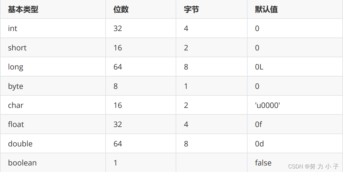
基本数据类型和对应的包装类
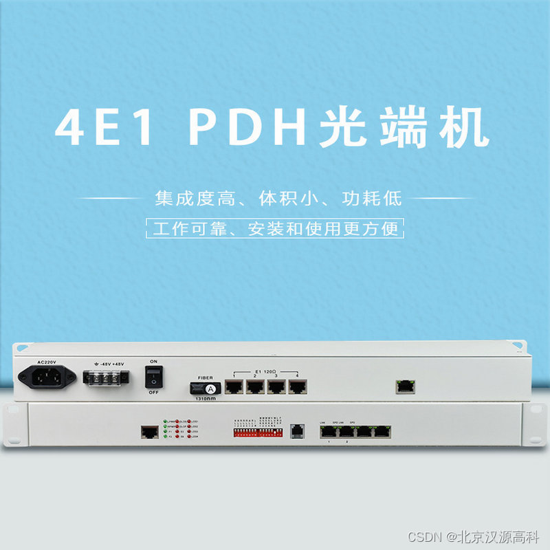
4E1 PDH光端机19英寸机架式单纤传输20km E1接口光纤网络光端机

Redis 入门-第一篇-数据结构与对象-简单动态字符串(SDS)

汉源高科1路千兆光口转4路千兆以太网电口千兆1光4电光纤收发器

"Dream of children's travel" in 2022, GAC Honda children's road safety charity travel entered the Northeast
随机推荐
公开课丨玩的就是短视频!今晚教你精准变现!
自动化或电气专业必备软件
坚持五件事,带你走出迷茫困境!
[cloud based co creation] overview of the IOT of Huawei cloud HCIA IOT v2.5 training series
在工作中学习的三个方法
一般的理财产品期限是几天啊?
切比雪夫不等式证明及应用
Voice data annotation tools and platforms
你真的理解LDO的输出电容吗!?
wc 统计已过时,cloc 每一行代码都有效
记录
目前 在哪里开户是最安全正规的?
Video data annotation tools and platforms (data annotation company)
如何在 FlowUs、Notion 等笔记软件中使用间隔重复记忆系统?
浅谈标注平台架构
【云舟说直播间】-数字安全专场明天下午正式上线
How to use note taking software flowus and note for interval repetition? Based on formula template
Proof and application of Chebyshev inequality
汉源高科8路电话+1路百兆以太网RJ11电话光端机 8路PCM电话光端机
Leetcode 1209. Delete all adjacent duplicates II in the string