当前位置:网站首页>Analog Electronic Technology
Analog Electronic Technology
2022-06-23 02:00:00 【A new doggerel imitating ancient times】
0. Analog circuits are classified by function :
- Amplification circuit
- Filter circuit
- Operational circuits
- Signal conversion circuit
- Signal generating circuit
- DC power supply
1. Common semiconductor devices
Semiconductors are substances with conductivity between conductors and insulators ( Such as silicon Si, germanium Ge), Most of them are tetravalent elements . There are intrinsic semiconductors and impurity semiconductors ( And then there is N type P Types ).
Intrinsic semiconductors have poor conductivity , Controlling the concentration of doped impurity elements can control the conductivity of impurity semiconductors .
- characteristic : photosensitive , Heat sensitivity , In addition, there are doping properties .
- PN junction : Unidirectional conductivity .
Characteristic parameters : Turn on the voltage , Forward conduction voltage drop , Reverse saturation current , Breakdown voltage .
Crystal diode
- Switching diodes
characteristic : Same as PN junction
analysis : Equivalent circuit method - Zener diode
Steady voltage ( Reverse breakdown voltage ), Steady current - Light emitting diode , Photodiode, etc
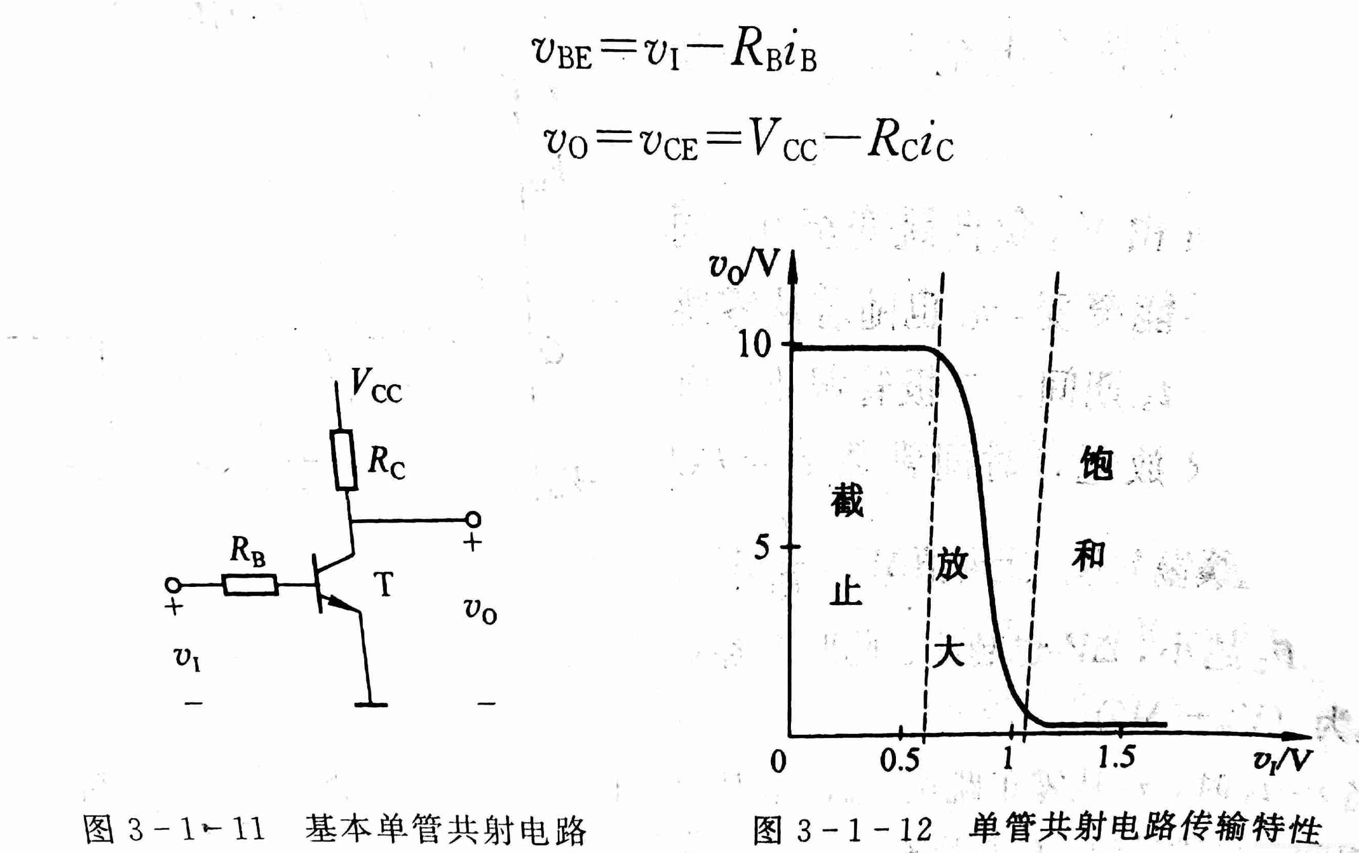
Crystal triode 
( The graph is NPN type )
classification :NPN/PNP; Common emitter / Common collector / Common base
Fluidity ( Current control current )
Amplification : When a small current is applied to the base of the triode , This current can be obtained at the collector β( Generally in 90~100) Times the collector current . The collector current varies with the base current , And a small change in the base current can cause a large change in the collector current , This is the amplification of triode .
Switch action : Saturation and cut-off states , Equivalent to on and off states .
Input features
( Same as diode )
output characteristic
Affected by temperature , A rise in temperature , The characteristic curve moves left and up .

Field effect tube (FET)
A semiconductor device that uses the electric field effect of the input circuit to control the current of the output circuit , The utility model belongs to a voltage controlled semiconductor device .It is divided into junction type and insulation grid type , Each type is divided into N Channel and P Ditch , Each channel of insulated grid type is divided into enhanced type and depleted type ; The source of the FET s、 Grid g、 Drain electrode d Corresponding to the emitter of triode respectively e、 The base b、 Collector c, Their functions are similar .
Field effect transistor and triode can form various amplifying circuits and switching circuits , However, the former has a simple manufacturing process , The utility model has the advantages of low power consumption , Good thermal stability , Wide working power supply voltage range and other advantages , So it is widely used in large scale and very large scale integrated circuits .
output characteristic

2. Amplification circuit
- Amplification is under the action of input signal , Through active components ( A transistor or FET ) Control and convert the energy of DC power supply , The output signal energy obtained by the load from the power supply is much larger than the energy provided by the signal source to the amplification circuit ; Amplification is characterized by power amplification , It shows that the output voltage is large or the output current is large , Or both ; The premise of amplification is no distortion .
- Static working point : When the DC power supply acts alone ( The input signal is 0) The base current of a transistor , Collector current ,b-e Voltage between tubes and tube voltage drop Uce.
Q The meaning of the dot :Q Point affects whether the circuit will be distorted and almost all the dynamic parameters of the amplification circuit .
The composition principle of amplifying circuit
- The core component is the active component , That is, transistor or field effect transistor .
- Value of power supply voltage 、 Polarity and other circuit parameters shall enable the transistor to operate in the amplification region 、 The FET operates in the constant current region , That is to establish a suitable static working point , Ensure that the circuit will not be distorted even if the input signal amplitude is the maximum .
- The input signal can effectively act on the input circuit of active components , That is, transistor b-e Loop and FET g-s loop ; The output signal shall be able to act on the load .
The main performance indexes of the amplifier circuit
- Magnification : The ratio of output variation amplitude to input variation amplitude , Or the ratio of the sinusoidal alternating current of the two , To measure the amplification capability of a circuit
- Input resistance R: Equivalent resistance seen from the input end , It reflects the magnitude of the current demanded by the amplification circuit from the signal source .
- Output resistance R.: The internal resistance of the equivalent output signal source viewed from the output , Explain the load capacity of the amplifier circuit .
- Maximum output voltage without loss .
- Lower limit 、 Upper eye cutoff frequency and passband : All are frequency response parameters , It reflects the adaptability of the circuit to the signal frequency .
- Maximum output power and efficiency .
Analysis method of amplification circuit
DC path / Communication channels ;
First static 、 Post dynamic ; Only static operating points are appropriate , Dynamic analysis makes sense .
- Static analysis . That is to solve the static working point Q, It can be estimated or illustrated .
- dynamic analysis . That is to solve the dynamic parameters and analyze the output waveform , Usually use h Parametric equivalent circuit calculates the amplification factor of small signal 、Ri and Ro, Analyze by graphic method Uo And distortion .
Multistage amplifier circuit
The voltage amplification factor of the multi-level amplification circuit is equal to the product of the voltage amplification factor of the circuits at all levels that make up it , When calculating the voltage amplification factor of a certain stage, the input resistance of the later stage should be taken as the load . Its input resistance is the input resistance of the first stage , The output resistance is the output resistance of the last stage . When the output waveform is distorted , The first step should be to determine from which level the distortion begins , Then judge the nature of distortion and eliminate it .
- Direct coupling
There is a temperature drift problem in the direct coupled amplifier circuit , Good low frequency characteristics , Able to amplify signals that change slowly , Easy integration . - Resistance capacitance coupling
The resistance capacitance coupling amplifier circuit uses the coupling capacitance “ Isolated DC , Through communication ”, Poor low frequency characteristics , Not easy to integrate , It is only used when the circuit is not composed of discrete components . - Transformer coupling
The transformer coupled amplifier circuit can realize impedance transformation , It is often used as tuning amplifier circuit or power amplifier circuit with large output power . - Photoelectric coupling
Photoelectric coupling mode has the function of electrical isolation , The circuit has strong anti-interference ability , It is suitable for signal isolation and long-distance transmission .
Integrated operational amplifier
Integrated operational amplifier is a high performance direct coupled amplifier , The voltage amplification factor can reach thousands of times . Looking from the outside , It can be equivalent to two terminal input 、 Differential amplifier with single output . Usually by input stage 、 Intermediate stage 、 The output stage and bias circuit are composed of four parts . Input stage multi-purpose differential amplifier circuit , The intermediate stage is a common shot ( Common source ) road , Output stage multi-purpose complementary output stage , The bias circuit is a multi-channel current source circuit .
- The basic differential amplifier circuit uses the symmetry of the parameters to compensate to suppress the temperature source ,
- The long tail amplifier and the differential amplifier with constant current source also use common mode negative feedback to suppress the temperature drift of each amplifier .
- Use common mode magnification 、 Differential mode magnification 、 Common mode rejection ratio 、 Input resistance and output resistance are used to describe the performance of the differential circuit .
- According to different grounding conditions of input and output terminals , Differential amplifier circuit has double input and single output , Single in double out , Single in single out , There are four connection methods of double in and double out .
Feedback in amplifier circuit
Output quantity in electronic circuit ( Output voltage or output current ) Some or all of them act on the input circuit through a certain circuit form , Used to influence the input amount ( Input voltage or input current of the amplifying circuit ) The action is called feedback . If result of the feedback changes output ( Or net input ) Reduce , It is called negative feedback ; conversely , It is called positive feedback . If the feedback exists in the DC path , It is called DC feedback ; If feedback exists in the communication path , It is called communication feedback .
- There are four configurations of AC negative feedback : Voltage series negative feedback , Voltage parallel negative feedback , Current series negative feedback , Current parallel negative feedback . The feedback quantity from the output voltage is called voltage feedback ; The feedback quantity from the output current is called current feedback ; If the input quantity 、 The superposition of feedback and net input in the form of voltage is called series feedback ; Phase superposition in the form of current is parallel feedback .
- When analyzing the feedback amplifier circuit ,“ Whether there is feedback ” It depends on whether there is a feedback path between the output circuit and the input circuit ; Positive and negative feedback are judged by instantaneous polarity method , The feedback results in a negative feedback when the net input decreases , What makes the net input increase is positive feedback ; The method to judge the negative voltage feedback and the negative current feedback is to make the output voltage of the amplifier circuit equal to 0, If the feedback quantity is 0, Voltage feedback , On the contrary, it is current feedback ; Series feedback and parallel feedback depend on the superposition form of dimensions .
- Deep negative feedback
Deep negative feedback is a feedback method in which the output signal is fed back to the input , Magnification expression Af=A/(1+AF) in , When 1+AF<1 when ,Af>A It means that positive feedback is introduced into the circuit , When 1+AF>1 when ,Af<A It means that negative feedback is introduced into the circuit ,|1+AF| >> 1 Is deep negative feedback , here 1+AF About equal to AF, be Af=A/AF=1/F, That is to say, the closed-loop magnification Af=A/(1+AF) About equal to 1/F, It shows that the magnification is almost determined by the feedback network , It has nothing to do with the basic amplification circuit . - The stability of the amplification factor can be improved by introducing AC negative feedback 、 Change the input resistance and output resistance 、 Broaden the frequency band 、 Reduce nonlinear distortion, etc . The negative feedback of different configurations has different effects on the performance of the amplifier circuit , The negative feedback of appropriate configuration should be introduced into the practical circuit ; The more stages the negative feedback amplifier circuit has , The deeper the feedback , The greater the possibility of self-excited oscillation , Therefore, three-stage negative feedback amplifier circuit is the most common .
Power amplifier circuit
- Transformer coupled power amplifier circuit
- Power amplifier circuit without output transformer (OTL)
- Power amplifier circuit without output capacitor (OCL)
2. Filter circuit
The active filter circuit is generally composed of RC Network and integrated operational amplifier .
3. Operational circuits
The integrated operational amplifier can realize the proportion of analog signal after introducing negative feedback , Addition and subtraction , Multiplication and division , Integro differential , Logarithmic exponent and other basic operations .
4. Signal generating circuit
Sine wave oscillation circuit
By amplifying circuit , Recruitment network , The positive feedback circuit is composed of a amplitude stabilizing link , According to the components used in the frequency selection network , Can be divided into :RC,LC And quartz crystal .Non sine wave generating circuit
By hysteresis comparator and RC The delay circuit consists of . Since the hysteresis comparator introduces positive feedback , Thus, the change of output voltage is accelerated , The delay circuit makes the output voltage of the comparator jump from high level to low level periodically , Then jump from low level to high level , Instead of staying in a steady state , So that the circuit will oscillate .
There is a square wave generating circuit 、 Triangle wave generating circuit and sawtooth wave generating circuit, etc .
5. Signal conversion circuit
- Voltage comparator : It can convert analog signals into binary signals with the characteristics of digital signals
Single limit comparator , hysteresis comparator , Window comparator .
- Waveform conversion circuit
The waveform conversion circuit uses a nonlinear circuit to change a waveform of one shape into another . The voltage comparator can change the periodically changing waveform into a rectangular wave , Integral operation circuit can change square wave into triangular wave , Differential operation circuit can change triangle wave into square wave ; The triangular wave can be changed into sawtooth wave by using the proportional operation circuit with controllable proportional coefficient , Triangle wave can be changed into sine wave by using filtering method or broken line method . - Signal conversion circuit
The signal conversion circuit is a signal processing circuit , Current can be converted into voltage by feedback method , It can also convert voltage into current ; AC signal can be converted into DC signal by using precision rectifier circuit , Use voltage - Frequency conversion circuit ( Voltage controlled oscillation circuit ) The DC voltage can be converted into a rectangular wave whose frequency is proportional to its value 、 Triangular wave or sawtooth wave voltage .
6. DC power supply
The DC regulated power supply consists of a rectifier circuit 、 Filter circuit and voltage stabilizing circuit . Rectifier circuit changes AC voltage into pulsating DC voltage , The filter circuit can reduce the pulsation and smooth the DC voltage , The function of the voltage stabilizing circuit is to keep the output voltage base unchanged when the grid voltage fluctuates or the load current changes .
- Rectifier circuit
Rectifier circuit has half wave and full wave , The most commonly used is the single-phase bridge rectifier circuit . - Filter circuit
The filter circuit usually has a capacitor filter 、 Inductive filtering and compound filtering . When the load current is large , Inductive filtering shall be used ; When the filtering effect is required to be high , Duplex filtering shall be used . - Voltage stabilizing circuit
It is divided into voltage stabilizing tube and voltage stabilizing circuit , Series regulated power supply and switch regulated circuit .
边栏推荐
- Debian10 configuring rsyslog+loganalyzer log server
- Uint8 serializing and deserializing pits using stringstream
- //1.9 char character variable operation
- 1. Mx6u bare metal program (4) - GPIO module
- HDU - 7072 double ended queue + opposite top
- Download and compile ROS source code
- 1. Mx6u bare metal program (6) - timer
- Function part
- Nuxt - auto generate dynamic route bug
- Triangle judgment (right angle, equilateral, general)
猜你喜欢

JS advanced part

Browser independent way to detect when image has been loaded

Campus network AC authentication failed

2D prefix and

Detailed explanation of clip attribute parameters

2022-1-12

Philosopher's walk gym divide and conquer + fractal

Constexpr keyword
Interviewer: with the for loop, why do you need foreach??

Branch and loop statements (including goto statements) -part1
随机推荐
Epoll introduction and principle explanation
Function part
Cmake simple usage
Classical questions of function recursion
Detailed explanation of GCC usage
Cut! 39 year old Ali P9 saved 150million
Muduo simple usage
1.3-1.4 web page data capture
C language game minesweeping [simple implementation]
165. cat climbing
Primary pointer part
1. Mx6u bare metal program (4) - GPIO module
Express framework installation and start service
Up the Strip
//1.16 getchar function
There is no corresponding change on the page after the code runs at the Chrome browser break point
Ansible practice of Nepal graph
Uniapp View Horizontal Center
Byte order: big endian vs little endian
Download and compile ROS source code