当前位置:网站首页>Three layer switching experiment
Three layer switching experiment
2022-06-24 18:13:00 【Kenneth~ Xiao Xiao】

step 1: analysis
1、 For the exchange part, you need to put lsw1 and lsw2 The two links of use eth-trunk Combine a link , Then create VLAN—— Divide VLAN——trunk main rd ——STP——SVI——VRRP——DHCP
2、 The connection part between the router and the switch uses ospf Protocol runthrough
3、 The public network is located in r1 Do on nat Address translation access public network
step 2: Divide ip
The intranet address is based on 172.16.0.0/16 Distribute , therefore
172.16.0.0/24 Used for switch and router network segment
172.16.0.0/30 r1 And lsw1 Connected network segment
172.16.0.4/30 r1 And lsw2 Connected network segment
172.16.1.0/24 Used to switch routing network segments
172.16.1.0/25 SVR1 The network segment
172.16.1.128/25 SVR2 The network segment
step 3: Simulation experiment diagram

step 4: Exchange part
1、 establish Eth-Trunk
lsw1:
[lsw1]interface Eth-Trunk 0
[lsw1-Eth-Trunk0]int g0/0/24
[lsw1-GigabitEthernet0/0/24]eth-trunk 0
[lsw1-GigabitEthernet0/0/24]int g0/0/23
[lsw1-GigabitEthernet0/0/23]eth-trunk 0
lsw2:
[lsw2]interface Eth-Trunk 0
[lsw2-Eth-Trunk0]int g0/0/24
[lsw2-GigabitEthernet0/0/24]eth-trunk 0
[lsw2-GigabitEthernet0/0/24]int g0/0/23
[lsw2-GigabitEthernet0/0/23]eth-trunk 0
2、 Create and divide VLAN
lsw1:
[Huawei]sysname lsw1
[lsw1]vlan 2
lsw2:
[Huawei]sysname lsw2
[lsw2]vlan 2
lsw3:
[Huawei]sysname lsw3
[lsw3]vlan 2
[lsw3-vlan2]q
[lsw3]int e0/0/4
[lsw3-Ethernet0/0/4]port link-type access
[lsw3-Ethernet0/0/4]port default vlan 2
[lsw3-Ethernet0/0/4]int e0/0/3
[lsw3-Ethernet0/0/3]port link-type access
[lsw3-Ethernet0/0/3]port default vlan 1

lsw4:
[Huawei]sysname lsw4
[lsw4]vlan 2
[lsw4-vlan2]int e0/0/3
[lsw4-Ethernet0/0/3]port link-type access
[lsw4-Ethernet0/0/3]port default vlan 1
[lsw4-Ethernet0/0/3]int e0/0/4
[lsw4-Ethernet0/0/4]port link-type access
[lsw4-Ethernet0/0/4]port default vlan 2

3、 establish trunk main rd
lsw1:
[lsw1]int g0/0/1
[lsw1-GigabitEthernet0/0/1]port link-type trunk
[lsw1-GigabitEthernet0/0/1]port trunk allow-pass vlan 2
[lsw1-GigabitEthernet0/0/1]int g0/0/2
[lsw1-GigabitEthernet0/0/2]port link-type trunk
[lsw1-GigabitEthernet0/0/2]port trunk allow-pass vlan 2
[lsw1-GigabitEthernet0/0/2]q
[lsw1]interface Eth-Trunk 0
[lsw1-Eth-Trunk0]port link-type trunk
[lsw1-Eth-Trunk0]port trunk allow-pass vlan 2
lsw2:
[lsw2]interface Eth-Trunk 0
[lsw2-Eth-Trunk0]port link-type trunk
[lsw2-Eth-Trunk0]port trunk allow-pass vlan 2
[lsw2-Eth-Trunk0]int g0/0/1
[lsw2-GigabitEthernet0/0/1]port link-type trunk
[lsw2-GigabitEthernet0/0/1]port trunk allow-pass vlan 2
[lsw2-GigabitEthernet0/0/1]int g0/0/2
[lsw2-GigabitEthernet0/0/2]port link-type trunk
[lsw2-GigabitEthernet0/0/2]port trunk allow-pass vlan 2
lsw3:
[lsw3]int e0/0/1
[lsw3-Ethernet0/0/1]port link-type trunk
[lsw3-Ethernet0/0/1]port trunk allow-pass vlan 2
[lsw3-Ethernet0/0/1]int e0/0/2
[lsw3-Ethernet0/0/2]port link-type trunk
[lsw3-Ethernet0/0/2]port trunk allow-pass vlan 2
lsw4:
[lsw4]int e0/0/1
[lsw4-Ethernet0/0/1]port link-type trunk
[lsw4-Ethernet0/0/1]port trunk allow-pass vlan 2
[lsw4-Ethernet0/0/1]int e0/0/2
[lsw4-Ethernet0/0/2]port link-type trunk
[lsw4-Ethernet0/0/2]port trunk allow-pass vlan 2
4、 To configure STP Of mstp Spanning tree protocol
lsw1:
[lsw1]stp mode mstp
[lsw1]stp enable
[lsw1]stp region-configuration
[lsw1-mst-region]region-name a
[lsw1-mst-region]instance 1 vlan 1
[lsw1-mst-region]instance 2 vlan 2
[lsw1-mst-region]active region-configuration
[lsw1-mst-region]q
[lsw1]stp instance 1 root primary
[lsw1]stp instance 2 root secondary

lsw2:
[lsw2]stp mode mstp
[lsw2]stp enable
[lsw2]stp region-configuration
[lsw2-mst-region]region-name a
[lsw2-mst-region] instance 1 vlan 1
[lsw2-mst-region] instance 2 vlan 2
[lsw2-mst-region] active region-configuration
[lsw2-mst-region]q
[lsw2]stp instance 1 root secondary
[lsw2]stp instance 2 root primary

lsw3:
[lsw3]stp mode mstp
[lsw3]stp enable
[lsw3]stp region-configuration
[lsw3-mst-region]region-name a
[lsw3-mst-region] instance 1 vlan 1
[lsw3-mst-region] instance 2 vlan 2
[lsw3-mst-region] active region-configuration
[lsw3-mst-region]q
[lsw3]int e0/0/3
[lsw3-Ethernet0/0/3]stp edged-port enable
[lsw3-Ethernet0/0/3]int e0/0/4
[lsw3-Ethernet0/0/4]stp edged-port enable
lsw4:
[lsw4]stp mode mstp
[lsw4]stp enable
[lsw4]stp region-configuration
[lsw4-mst-region]region-name a
[lsw4-mst-region] instance 1 vlan 1
[lsw4-mst-region] instance 2 vlan 2
[lsw4-mst-region] active region-configuration
[lsw4-mst-region]q
[lsw4]int Eth0/0/3
[lsw4-Ethernet0/0/3]stp edged-port enable
[lsw4-Ethernet0/0/3]int e0/0/4
[lsw4-Ethernet0/0/4]stp edged-port enable
5、 To configure SVI
lsw1:
[lsw1]interface Vlanif 1
[lsw1-Vlanif1]ip address 172.16.1.1 25
[lsw1-Vlanif1]q
[lsw1]interface Vlanif 2
[lsw1-Vlanif2]ip address 172.16.1.129 25
lsw2:
[lsw2]interface Vlanif 1
[lsw2-Vlanif1]ip address 172.16.1.2 25
[lsw2-Vlanif1]q
[lsw2]interface Vlanif 2
[lsw2-Vlanif2]ip address 172.16.1.130 25

6、 To configure vrrp
lsw1:
[lsw1]interface Vlanif 1
[lsw1-Vlanif1]vrrp vrid 1 virtual-ip 172.16.1.126
[lsw1-Vlanif1]vrrp vrid 1 priority 110
[lsw1-Vlanif1]vrrp vrid 1 track interface g0/0/3 reduced 11
[lsw1-Vlanif1]q
[lsw1]interface Vlanif 2
[lsw1-Vlanif2]vrrp vrid 1 virtual-ip 172.16.1.254

lsw2:
[lsw2]interface Vlanif 1
[lsw2-Vlanif1]vrrp vrid 1 virtual-ip 172.16.1.126
[lsw2-Vlanif1]q
[lsw2]interface Vlanif 2
[lsw2-Vlanif2]vrrp vrid 1 virtual-ip 172.16.1.254
[lsw2-Vlanif2]vrrp vrid 1 priority 110
[lsw2-Vlanif2]vrrp vrid 1 track interface g0/0/3 reduced 11

7、 To configure DHCP
lsw1:
[lsw1]dhcp enable
[lsw1]ip pool v1
[lsw1-ip-pool-v1]network 172.16.1.0 mask 25
[lsw1-ip-pool-v1]gateway-list 172.16.1.126
[lsw1-ip-pool-v1]dns-list 114.114.114.114
[lsw1-ip-pool-v1]q
[lsw1]ip pool v2
[lsw1-ip-pool-v2]network 172.16.1.128 mask 25
[lsw1-ip-pool-v2]gateway-list 172.16.1.254
[lsw1-ip-pool-v2]dns-list 114.114.114.114
[lsw1-ip-pool-v2]q
[lsw1]interface Vlanif 1
[lsw1-Vlanif1]dhcp select global
[lsw1-Vlanif1]q
[lsw1]interface Vlanif 2
[lsw1-Vlanif2]dhcp select global
lsw2:
[lsw2]dhcp enable
[lsw2]ip pool v1
[lsw2-ip-pool-v1] gateway-list 172.16.1.126
[lsw2-ip-pool-v1] network 172.16.1.0 mask 255.255.255.128
[lsw2-ip-pool-v1] dns-list 114.114.114.114
[lsw2-ip-pool-v1]ip pool v2
[lsw2-ip-pool-v2] gateway-list 172.16.1.254
[lsw2-ip-pool-v2] network 172.16.1.128 mask 255.255.255.128
[lsw2-ip-pool-v2] dns-list 114.114.114.114
[lsw2-ip-pool-v2]q
[lsw2]interface Vlanif 1
[lsw2-Vlanif1]dhcp select global
[lsw2-Vlanif1]q
[lsw2]interface Vlanif 2
[lsw2-Vlanif2]dhcp select global
pc1:

pc2:
pc3:

pc4:

step 5:ospf The partial
1、 To configure ospf Part of the ip Address
r1:
[r1]int g0/0/0
[r1-GigabitEthernet0/0/0]ip address 172.16.0.1 30
[r1-GigabitEthernet0/0/0]int g0/0/1
[r1-GigabitEthernet0/0/1]ip address 172.16.0.5 30
lsw1:
[lsw1]vlan 99
[lsw1-vlan99]q
[lsw1]interface Vlanif 99
[lsw1-Vlanif99]ip address 172.16.0.2 30
[lsw1-Vlanif99]q
[lsw1]int g0/0/3
[lsw1-GigabitEthernet0/0/3]port link-type access
[lsw1-GigabitEthernet0/0/3]port default vlan 99
lsw2:
[lsw2]vlan 99
[lsw2-vlan99]q
[lsw2]interface Vlanif 99
[lsw2-Vlanif99]ip address 172.16.0.6 30
[lsw2-Vlanif99]q
[lsw2]interface g0/0/3
[lsw2-GigabitEthernet0/0/3]port link-type access
[lsw2-GigabitEthernet0/0/3]port default vlan 99
2、 To configure ospf agreement :
r1:
[r1]ospf 1 router-id 1.1.1.1
[r1-ospf-1]area 0
[r1-ospf-1-area-0.0.0.0]network 172.16.0.1 0.0.0.0
[r1-ospf-1-area-0.0.0.0]network 172.16.0.5 0.0.0.0

lsw1:
[lsw1]ospf 1 router-id 2.2.2.2
[lsw1-ospf-1]area 0
[lsw1-ospf-1-area-0.0.0.0]network 172.16.0.2 0.0.0.0
[lsw1-ospf-1-area-0.0.0.0]area 1
[lsw1-ospf-1-area-0.0.0.1]network 172.16.1.1 0.0.0.0
[lsw1-ospf-1-area-0.0.0.1]network 172.16.1.129 0.0.0.0
[lsw1-ospf-1-area-0.0.0.1]q
[lsw1-ospf-1]silent-interface g0/0/1
[lsw1-ospf-1]silent-interface g0/0/2
[lsw1-ospf-1]silent-interface Vlanif 2

lsw2:
[lsw2]ospf 1 router-id 3.3.3.3
[lsw2-ospf-1]area 0
[lsw2-ospf-1-area-0.0.0.0]network 172.16.0.6 0.0.0.0
[lsw2-ospf-1-area-0.0.0.0]area 1
[lsw2-ospf-1-area-0.0.0.1]network 172.16.1.2 0.0.0.0
[lsw2-ospf-1-area-0.0.0.1]network 172.16.1.130 0.0.0.0
[lsw2-ospf-1-area-0.0.0.1]q
[lsw2-ospf-1]silent-interface g0/0/1
[lsw2-ospf-1]silent-interface g0/0/2
[lsw2-ospf-1]silent-interface Vlanif 2

3、 Issue default and summary optimization
r1:
[r1]ip route-static 0.0.0.0 0 12.1.1.2
[r1]ospf 1
[r1-ospf-1]default-route-advertise
lsw1:
[lsw1-ospf-1]area 1
[lsw1-ospf-1-area-0.0.0.1]asbr-summary 172.16.1.0 255.255.255.0

lsw2:
[lsw2-ospf-1]area 1
[lsw2-ospf-1-area-0.0.0.1]asbr-summary 172.16.1.0 255.255.255.0

step 6: Public network part
1、 Configure the address of the public network
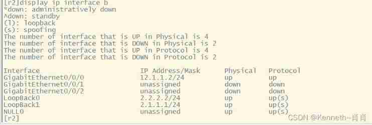
r2 The public network part of the router is configured :
system-view
[r2]int g0/0/0
[r2-GigabitEthernet0/0/0]ip address 12.1.1.2 24
[r2-GigabitEthernet0/0/0]int lo0
[r2-LoopBack0]ip address 2.2.2.2 24
[r2-LoopBack0]int lo1
[r2-LoopBack1]ip address 2.1.1.1 24
r1 The public network part of the router is configured :
system-view
[r1]int g0/0/2
[r1-GigabitEthernet0/0/2]ip address 12.1.1.1 24

2、 Yes r1 Visit the address of the public network to do nat address translation
[r1]acl 2000
[r1-acl-basic-2000]rule permit source any
[r1-acl-basic-2000]q
[r1]int g0/0/2
[r1-GigabitEthernet0/0/2]nat outbound 2000
3、 test

step 7: test
pc1:

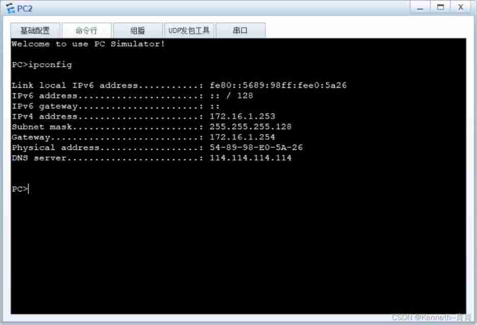
pc2:

pc3:

pc4:

边栏推荐
- It is often blocked by R & D and operation? You need to master the 8 steps before realizing the requirements
- Yum to install warning:xxx: header V3 dsa/sha1 signature, key ID 5072e1f5: nokey
- Leveldb source code analysis -- open the database
- Eight recommended microservice testing tools
- Two micro service interviews where small companies suffer losses
- Regression testing strategy for comprehensive quality assurance system
- How does the chief information security officer discuss network security with the enterprise board of directors
- 股票网上开户安全吗?应该怎么办理?
- Tencent cloud won the "trusted cloud technology best practice - virtualization"
- Top ten popular codeless testing tools
猜你喜欢

How does the chief information security officer discuss network security with the enterprise board of directors

13 skills necessary for a competent QA Manager
![[NLP] 3 papers on how Stanford team builds a better chat AI](/img/f1/1c2ff31a728152395618800600df45.jpg)
[NLP] 3 papers on how Stanford team builds a better chat AI
Paper sharing | self supervised learning paper jointly released by Yann Lecun and read by engineers

The 'ng' entry cannot be recognized as the name of a cmdlet, function, script file, or runnable program. Check the spelling of the name. If you include a path, make sure the path is correct, and then

LC 300. Longest increasing subsequence

Ten excellent business process automation tools for small businesses

Exception: Gradle task assembleDebug failed with exit code 1

How can programmers reduce bugs in development?

Error reported after NPM I

随机推荐
SQL basic tutorial (learning notes)
Restcloud ETL extracting dynamic library table data
Etching process flow for PCB fabrication
Leveldb source code analysis -- writing data
基于BGP实现纯三层容器网络方案
How do yaml files and zmail collide with the spark of the framework, and how can code and data be separated gracefully?
-Bash: wget: command not found
Millions of dollars worth of NFT were stolen in the attack, and Google issued an emergency warning to 3.2 billion users worldwide | February 21 global network security hotspot
What is the problem that the data is not displayed on the login web page after the configuration of the RTSP video security intelligent monitoring system easynvr is completed
1. Leveldb getting started
Top ten popular codeless testing tools
Three indicators to help you measure the effectiveness of digital transformation
How can programmers reduce bugs in development?
LC 300. Longest increasing subsequence
March 27, 2021: give you a head node of the linked list, and rotate the linked list
Why are more and more people studying for doctors? Isn't it more and more difficult to graduate a doctor?
He "painted" what a smart city should look like with his oars
Go collaboration and pipeline to realize asynchronous batch consumption scheduling task
C language - structure II
电子元器件行业B2B电商市场模式、交易能力数字化趋势分析