当前位置:网站首页>Electronics: Lesson 009 - Experiment 7: study relays
Electronics: Lesson 009 - Experiment 7: study relays
2022-06-25 08:05:00 【acktomas】
experiment 7: Research relay
The next step in exploring the switch is to use the remote switch .“ remote control ” The switch is opened or closed according to the signal you send . This switch is called a relay , Because it passes instructions from one part of the circuit to another .
The relay is usually powered by a low voltage 、 Low current control , Used to switch high voltage or high current .
Relays are very useful . for example , When starting the car , A smaller, cheaper ignition switch sends a small signal to a relay near the starting motor through a thin, cheap wire . The relay passes through a shorter section 、 More thick 、 More expensive , Be able to bear 100 A A current conductor starts a motor .
Empathy , If you lift the lid of an old top opening washing machine during its rotation , A small switch is closed , It sends a small signal along a thin wire to the relay . The switch controls the large motor that rotates the washing bucket, which is the task of the relay .
Items needed
- A multimeter 、 Multi purpose tools
- 9 V The battery 1
- Double pole double throw 9 V DC relay 2
- Single pole single throw touch switch
- Test leads with spring clips at both ends 5 strip
Relay
I suggest you use a relay with two pins at one end , There are six pins on the other end . These six pins are divided into two rows and three columns , Pictured 2-49 Shown ( The relay is reversed , Pin up ). If you buy two relays , One of them can be used to study ( Open it , Observe the internal structure ). If you operate very carefully , The relay should then be usable . If it is accidentally damaged , It can also be used as a spare part .

Be careful : Polarity problem
Some relays require very high voltage applied to the internal coil . When current flows in a certain direction in the coil , Everything is all right , But if you reverse the positive and negative connections ( Reverse polarity ), The relay stops working .
If the polarity requirements are not clearly stated in the data sheet of the relay , That's annoying . The relay I propose to use has no specific requirements for polarity .
step
Test leads and touch switches ( Button switch ) Pictured 2-49 Connection shown .( Be careful , The devices in the figure are not drawn to scale .) Close push button switch , hold 9 V The voltage is applied to two separate pins , You should be able to hear very light “ click ” The sound . Turn off the switch , It should be heard again “ click ” The sound .( If you don't hear well , You can gently touch the relay with your fingertips , When “ click ” When the sound appears , A faint vibration should be felt .)
What happened? ? A multimeter can help you with your research . Set the multimeter to measure continuity , Put the two pens together ,
Verify that the multimeter is working . If there is no beep , It is not set to measure continuity , Or the battery is dead , Or there is a probe inserted into the wrong socket .
Now? , Pictured 2-50 Shown , Press the lead on the pin , Press the button . While pressing the button , The multimeter beeps . This test tells you , When applying voltage to the pair of pins closest to you , There must be some switches inside the relay that are closed .

however , It may be difficult to press the button while pressing the pin with the lead . If so , You can follow the picture 2-51 Shown in
Law , Add several test leads . A probe is clamped at one end of each lead , Clamp the relay pin at the other end , In this way, your hands will be free from the trouble of holding the pen .

Now move the red test lead from the relay pin farthest away from you to the empty pin adjacent to it . You'll find that , The response of the multimeter is the opposite of the last time , A beep will sound when the button is not pressed , Press the button to stop the buzzer .
What happened inside the relay
chart 2-52 Shows when the button is pressed , Perspective photo of relay interior . There is a coil at the bottom of the relay , It generates a magnetic field , The magnetic field controls a pair of switches inside . The coil actuates the switch on the right , Make pins A and C Form a connection inside , So the multimeter beeps .

You may wonder why the coil in the relay pushes the internal switch away from it . as a result of , There is a mechanical linkage in the relay , It can convert tension into thrust . When I talk about turning on the relay later , You can see this .
chart 2-53 Shows what happens when the button is not pressed . The switch contacts are released , Connect to another pair of contacts , To break off A and B Connection between , stay B and C Form a connection between . When there is no current flowing through the relay coil , The switch remains in this position .
Other relays
I believe the pin function I described is the most common for relays of this size , But there are some exceptions . When you first saw the double pole double throw relay , How to determine the internal structure —— Apply voltage to the coil , At the same time, measure each pair of different pins with a multimeter . Use exclusion , You can know how the pins are connected .
You can also read the manufacturer's data sheet . It should include the following figure 2-21 The chart shown here . Is this all you should know about relays ? No , I just touched the surface .
- Some relays are latching , That is, when there is no electricity , The internal switch will remain in any position . A latching relay usually has two coils to operate the switch to close in both directions . I won't use this relay .
- Some relays have two poles , There is only one ; Some are double throw , Some are single throw
- Some coils are controlled by alternating current , Some use DC control , And as mentioned above , Some DC coils require the correct polarity of the applied DC voltage .
As always, , The data sheet should provide the necessary information .
chart 2-54 The circuit diagram symbols of various relays are shown .A It is a single pole single throw relay ,B It is a single pole double throw relay ,C It is a single pole single throw relay , Painting has become my favorite form , Use a white rectangle to remind you that these components are enclosed in one component .D It is a single pole double throw relay ,E It is a double pole double throw relay ,F It is a single pole double throw latching relay .

When power is not applied , The internal switch of the relay is usually plotted as being in a relaxed state , The drawing method of locking relay is different , Its switch position is arbitrary .
What you are detecting is a small signal relay , It cannot control the on-off of large current . Large relays can control several amperes of current . Be sure to select a relay whose rated current is not less than the maximum current of the circuit , Because the overload of the relay will produce sparks , This will quickly damage the contacts .
In future experiments , You will find some practical uses for relays —— For example, in the general application of the family safety system . Before touching this system , I'll show you how to turn a relay into a buzzing oscillator . But first, we need to understand the internal structure of the relay .
Disassemble the relay
If you're in a hurry , You can use as shown in the figure 2-55 Sum graph 2-56 Disassemble the relay as shown in . however , Generally speaking , Use the most common equipment ( Art knife or multi-purpose knife ) It will be better .

chart 2-57 Sum graph 2-58 Shows the method I like to use : Cut the edges of the plastic shell obliquely , Until you see a thin crack . Don't cut any more , Because the internal parts are very close to the blade . Now clear the cut surface . Repeat on the remaining edges of the housing , If you're really careful , Even if the components inside the relay are exposed , The coil can also work when it is energized .
chart 2-59 A simplified diagram showing the internal components of a standard relay . coil A Generate magnetic attraction , Pull the lever B Move down . Plastic extension lever C Squeeze the elastic strip outward , Push the pole of the relay D Move between contacts .( This relay is slightly different from the structure recommended in this experiment , But the principle is roughly the same .)

You can compare this diagram with a relay I took apart , Pictured 2-60 Shown .
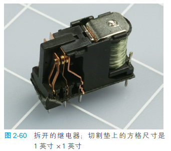
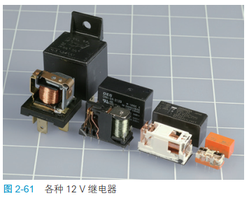
chart 2-61 The various sizes of relays with their housings removed are shown . Happen to happen , They are all there 12 V Working under DC . The leftmost car relay is the simplest , It's the easiest to understand , Because its design does not consider the size of the package too much . Smaller relays have a more sophisticated design , More complicated , It's harder to understand . Usually , Smaller relays are designed to make and break less current than larger relays , But there are exceptions .
Basic knowledge of : Relay terminology
Coil voltage When the relay is energized , Voltage to be obtained . The voltage can be AC or DC .
Set the voltage Is the minimum voltage at which the relay can close the switch . This voltage is slightly less than the ideal coil voltage . actually , The operating voltage of the relay may be lower than the set voltage , But the setting voltage can tell you what the minimum voltage is to ensure the normal operation of the relay .
Working current Is the power consumption of the coil after the relay is energized , It is generally expressed in milliamperes . Sometimes the power consumed is expressed in milliwatts .
Breaking capacity It is the maximum current that the switch inside the relay can control the on-off without damage . Usually , This term is used to describe resistive loads , Resistive load refers to passive components such as incandescent bulbs . When you use a relay to turn on the motor , Inductive load is introduced into the circuit , It will produce huge initial surge current before the motor reaches normal speed . Switching off the motor will generate another surge current . If the data sheet of the relay does not indicate its ability to handle inductive loads , The rule of thumb is : It is assumed that the current of the motor at startup is twice its normal working current .
边栏推荐
- Looking for b-end product manager after years? I almost ruined myself
- TCP MIN_RTO 辩证考
- 50 pieces of professional knowledge of Product Manager (IV) - from problem to ability improvement: amdgf model tool
- Opencv minimum filtering (not limited to images)
- 环网冗余式CAN/光纤转换器的CAN光端机在消防火灾联网报警系统中的应用
- 取消word文档中某些页面的页眉
- 2160. minimum sum of the last four digits after splitting
- Luogu p5994 [pa2014]kuglarz (XOR thinking +mst)
- Electronics: Lesson 012 - Experiment 13: barbecue LED
- 协议和服务的区别?
猜你喜欢

一文了解 | 革兰氏阳性和阴性菌区别,致病差异,针对用药

Electronics: Lesson 012 - Experiment 13: barbecue LED

Dietary intervention reduces cancer treatment-related symptoms and toxicity

【论文学习】《VQMIVC》

Cifar-10 dataset application: quick start data enhancement method mixup significantly improves image recognition accuracy

Electronics: Lesson 014 - Experiment 15: intrusion alarm (Part I)

Vscode is good, but I won't use it again

Modeling and fault simulation of aircraft bleed system

用函数的递归来解决几道有趣的题

环网冗余式CAN/光纤转换器的CAN光端机在消防火灾联网报警系统中的应用
随机推荐
【莫比乌斯反演】
Mining microbial dark matter -- a new idea
取消word文档中某些页面的页眉
To understand the difference between Gram-positive and Gram-negative bacteria and the difference in pathogenicity
2265. number of nodes with statistical value equal to the average value of subtree
Linux上oracle和mysql的启动,关闭,重启
Luogu p1073 [noip2009 improvement group] optimal trade (layered diagram + shortest path)
【补题】2021牛客暑期多校训练营6-n
TCP的那点玩意儿
Neural network and deep learning-3-simple example of machine learning pytorch
2021ICPC网络赛第一场
电子学:第010课——实验 8:继电振荡器
C # set up FTP server and realize file uploading and downloading
Electronics: Lesson 012 - Experiment 11: light and sound
TCP 加速小记
Can bus working condition and signal quality "physical examination"
用函数的递归来解决几道有趣的题
C disk drives, folders and file operations
电子学:第009课——实验 7:研究继电器
协议和服务的区别?