当前位置:网站首页>[defect detection] automatic defect detection of printed circuit board based on Matlab GUI [including Matlab source code 1912]
[defect detection] automatic defect detection of printed circuit board based on Matlab GUI [including Matlab source code 1912]
2022-06-26 02:22:00 【Poseidon light】
One 、 Introduction to automatic defect detection of printed circuit board
Our country is PCB A big producer , According to the world electronic circuit Council WECC Statistics of each association [1],2007 In Chinese mainland PCB The output value accounts for% of the global total output value 27.9%, Just one year is better than 2006 An increase of 17.0%. But in our country PCB With the rapid development of the industry , There are also huge challenges , That's it PCB Quality problems . In the production process, any process or even PCB Anything on 1 Any problem with one line will lead to the whole PCB Scrap of plates . High scrap rates increase production costs . How to find and reduce the scrap rate in time , Is currently all PCB The urgent needs of the manufacturers . In the current manual visual inspection 、 Online testing and many other detection methods , Automatic optical detection AOI(Automatic Optic Inspection) At cost 、 efficiency 、 Reliability and other aspects show unique advantages . In this paper, a set of PCB Automatic defect detection system . This paper mainly introduces the software implementation of the system .
1 System flow
The system software composition is shown in the figure 1 Shown . First, shoot on the same workbench PCB Standard drawing , This is to try to keep the same object distance between the photographed standard map and the map to be measured 、 Focal length, etc , To reduce the time-consuming of image registration and minimize the error , Improve recognition rate . Median filter is applied to the standard image to filter out the noise and smooth the image , Then save the standard drawing . Open the measured map during detection , First, carry out pretreatment such as noise filtering , Then image registration is carried out by positioning circle ; Then do the subtraction operation , The feature of travel shadow is separated by threshold transformation . Because the image matching can not completely achieve one-to-one pixel correspondence and the threshold segmentation is not perfect , There may be non defective parts in the binary graph after threshold transformation . If these parts cannot be removed , It will cause false detection . Therefore, morphological transformation is also needed to filter out noise . Finally, the geometric characteristics of the separated defect targets are counted and a conclusion is drawn .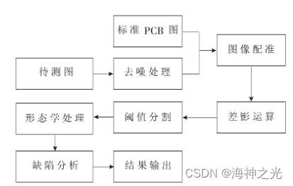
chart 1 Software processing flow of the system
2 Image preprocessing and registration
2.1 Image denoising operation
The image is forming 、 transmission 、 In the process of receiving and processing , There is inevitably external and internal interference , Such as the non-uniformity of sensitivity of sensitive elements in the photoelectric conversion process 、 Quantization noise in digital process 、 Errors in the transmission process and human factors , Will cause noise [2]. At present, the median filter is an ideal algorithm for denoising . Median filter is a nonlinear signal processing method , The principle is as follows : Suppose there is 1 One dimensional sequence f1,f2,f3,…,fn, Take the window length ( points ) by m(m It's odd ). Median filter the sequence , That is to extract from the sequence successively m Number fi-v,…,fi-1,fi,fi+1,…,fi+v, among fi Is the center point value of the window ,v=(m-1)/2. And then m Point values are sorted by their numerical value , Take the middle number as the filter output , Expressed as :yi=med{fi-v,…,fi-1,fi,fi+1,…,fi+v}, among i∈Z,v=(m-1)/2. chart 2 The comparison effect of the pictures before and after median filtering is shown . thus it can be seen , Median filter is very important to filter out noise , Retaining feature information has an ideal effect .
chart 2 Median filter effect map
2.2 Image registration
The image registration is based on different time 、 The same scene with different sensors or different perspectives 2 The process of matching images or multiple images . Image registration is usually carried out by calculating the similarity of images , The image similarity is evaluated by calculating the similarity measure . Similarity measures are divided into cross-correlation similarity measures 、 Measure based on Fourier analysis and sequential similarity detection . The cross-correlation similarity measure is the most basic similarity measure , The principle is as follows : Suppose there is a template T And search graph S,Si,j Represents the search graph covered by the template [3], among i、j Indicate location . Then the cross-correlation similarity is :
Owned by one becomes :
T and Si,j The more similar , be R(i,j) The bigger it is , When T and Si,j When completely similar ,R(i,j)=1, Therefore, according to R(i,j) To judge the size of T and Si,j The degree of similarity .
2.3 Geometric matching
2.3.1 Matching principle
In this paper, the difference shadow method is used for defect detection , Subtraction detection must be based on the basic correspondence between the pixels of the image to be measured and the standard image . So the core of the subtraction method is the geometric matching of the image . The matching between the map to be measured and the standard map is usually solved by setting positioning marks , That is to say PCB The diagonal part of the board is marked by adding a specific figure , When positioning, the figure is scaled by the geometric position difference between the standard drawing and the target drawing board 、 The geometric operations of translation and rotation are used to realize the one-to-one correspondence between the pixels of the map to be measured and the standard map . The effect of geometric matching largely depends on the position and size of the positioning drawing . Usually, a circle with regular shape is selected for positioning , Not only because the coordinates of the center of the circle have a good positioning function , It is also because the research on circle detection has been relatively mature , It is easy to detect the characteristic size of the circle .
2.3.2 Circle detection
At present, the vast majority of circle detection is through Hough Transform to .Hough Transformation is to use the corresponding relationship between image space and parameter space , Transform the detection problem of image control into parameter space , The detection task is completed by simply accumulating statistics in the parameter space .Hough The circular detection principle of the transformation, the equation of the circle is expressed as :
In the parameter space 1 A three-dimensional cumulative array A(a,b,r), Calculate each 1 A triad (a,b,r), Also on A Add up :
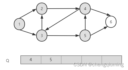
If the radius r Fix , Then the correspondence between the parameter space and the image space is shown in Figure 3 Shown . The black part corresponds to a point on the circumference in the image space , The circle is the possible center position . therefore , The points of common circles in the image space correspond to the same point in the parameter space , That is, points in image space correspond to circles in parameter space , Points in parameter space correspond to circles in image space . The implementation of the algorithm also makes use of this feature .
chart 3 Hough Parameter space of transformation
If the circle is detected directly by this method , Because the pixels of the whole image need to be calculated point by point and judged , It will take a lot of system time , Therefore, the speed can not meet the real-time requirements . be based on Hough Circle detection method of transformation [5] By first graying the image 、 Denoise 、 Edge detection, morphological operation and other preprocessing , Then by using multi-dimensional array instead of circular calculation Hough Transformation , It can greatly improve the detection speed and accuracy .
2.3.2 Geometric transformation of images
chart 5 As shown in the for PCB Position of the plate positioning circle , among A(x1,y1)、B(x2,y2) Respectively 2 Coordinates of the center of a positioning circle . There are positioning circles on the standard plate and the plate to be tested , Therefore, the deviation of the map to be measured due to camera distortion or workbench vibration can be passed through A、B Coordinate deviation shall be adjusted by geometric transformation of the measured drawing , The adjustment steps are :
(1) Calculate the horizontal deflection angle of the positioning circle center of the drawing to be measured θAB And standard drawings θ′AB. If θAB≠θ′AB, Then rotate the mapping to be measured . The rotation angle is θAB―θ′AB( Clockwise is positive ).
(2) Calculate the distance between the positioning center of the drawing to be measured LAB And standard drawings L′AB, If LAB≠L′AB, Then zoom and transform the map to be measured . Zoom by n=L′AB/LAB(n>1 Represents zoom ).
(3) Calculate the map to be measured 2 The midpoint coordinates of the center line of the positioning circle pass through (1)、(2) Coordinates after two-step operation D. take D With the standard drawing D′ Compare , If it's not equal , be X Direction translation Dx′-Dx,Y Direction translation Dy′-Dy( The upper left corner of the screen is the origin ,X The axis is facing right ,Y The positive direction of the shaft is downward ).
chart 5 Positioning circle
3 defect detection
3.1 Threshold transformation
Geometric registration performs the difference operation between the standard map and the map to be measured , The obtained difference image is shown in Figure 6(a) Shown , This graph is not a binary graph , For statistical identification of defects , It needs to be transformed into a binary graph by threshold segmentation . Image segmentation methods can be divided into fixed threshold segmentation and automatic threshold segmentation . Fixed threshold segmentation is a method of binarization through a certain threshold or a selected threshold during human operation . Because this method is very inflexible and not automatic , So this paper mainly discusses automatic threshold segmentation , The global threshold is selected for segmentation by searching histogram . Such methods mainly include : Shuangfeng law 、 The threshold of maximum internal variance (OSTU) Law 、P_tittle Threshold segmentation method 、 Maximum entropy method, etc . This paper uses the maximum internal variance threshold (OSTU) Law [5]. The basic idea of this law is : The optimal threshold should maximize the separability between different classes . The histogram of the image to be processed is divided into 2 Group , When divided into 2 When the variance between groups is the largest , Determine the threshold .OSTU The segmented image is shown in the figure 6(b) Shown .
chart 6 Subtraction operation and threshold segmentation effect
3.2 Morphological transformation
Due to the error in the registration process and the tiny distortion defect of the image itself , Therefore, the image after subtraction operation will have non defective parts that cannot be eliminated . Pictured 7 Shown , There is little difference between the gray value of the defect and the gray value of the defect , This part of noise must also exist after threshold segmentation , If these parts are not eliminated , It will cause false detection . These noises can be eliminated by morphological transformation .
chart 7 After morphological operation
Morphology is also called mathematical morphology [6], It is a mathematical method for analyzing geometric shapes , Is based on set algebra , The science of quantitatively describing the structure of sets by means of set theory . The most basic morphological operators are : corrosion (Erosion)、 inflation (Delation)、 open (Opening) And closed (Closing). Due to the need to filter out noise , Corrosion and open operations are used in this paper .
about 1 A given target image X and 1 Structural elements S, If S Move on the image , In each of the 1 Current positions x,S[x] as long as 3 All possible states :S[x]⊆X、S[x]⊆Xc、S[x]∩X And S[x]∩Xc None of them are empty . It's satisfying S[x]⊆X The point of x The largest set of correlation points between all the structural elements of the image and the image , This point set is called S Yes X The corrosion of , Write it down as XӨS. Defined in the form of a set as :XӨS={x|S[x]⊆X}. The function of the boundary of the object is to eliminate the corrosion point , Objects smaller than structural elements can be removed , Select structural elements of different sizes , You can remove objects of different sizes .
Corrosion can be seen as an image X Every time 1 Structural elements S Congruent S[x] Shrink to point x. conversely , take X Every... In 1 A little bit X Expand to S[x]. This is the expansion operation , It is defined as... In a set way :XӨS={x S[x]∩x≠0}. Contrary to corrosion , The function of expansion operation is to merge the background points around the image into the object .
Open and close operations are defined on the basis of corrosion and expansion . The open operation is to etch the image first and then expand it . The closed operation is to expand the image first and then erode it .
Through this 4 The combination of morphological operators can perform image segmentation 、 feature extraction 、 edge detection 、 Image filtering 、 Image enhancement and restoration . chart 7 It is to divide the graph after the threshold 1 Secondary corrosion calculation and 1 The result of the second open operation . Left behind 4 Is the binary diagram of the defect location on the target circuit board .
Two 、 Partial source code
function varargout = Mainyinshua(varargin)
% Prepared by OON CHEE YEE, 27737268
% MAINYINSHUA MATLAB code for Mainyinshua.fig
%      MAINYINSHUA, by itself, creates a new MAINYINSHUA or raises the existing
%      singleton*.
%
%      H = MAINYINSHUA returns the handle to a new MAINYINSHUA or the handle to
%      the existing singleton*.
%
%      MAINYINSHUA('CALLBACK',hObject,eventData,handles,...) calls the local
%      function named CALLBACK in MAINYINSHUA.M with the given input arguments.
%
%      MAINYINSHUA('Property','Value',...) creates a new MAINYINSHUA or raises the
%      existing singleton*.  Starting from the left, property value pairs are
%      applied to the GUI before Mainyinshua_OpeningFcn gets called.  An
%      unrecognized property name or invalid value makes property application
%      stop.  All inputs are passed to Mainyinshua_OpeningFcn via varargin.
%
%      *See GUI Options on GUIDE's Tools menu.  Choose "GUI allows only one
%      instance to run (singleton)".
%
% See also: GUIDE, GUIDATA, GUIHANDLES

% Edit the above text to modify the response to help Mainyinshua

% Last Modified by GUIDE v2.5 23-Jun-2022 19:33:32

% Begin initialization code - DO NOT EDIT
gui_Singleton = 1;
gui_State = struct('gui_Name',       mfilename, ...
                   'gui_Singleton',  gui_Singleton, ...
                   'gui_OpeningFcn', @Mainyinshua_OpeningFcn, ...
                   'gui_OutputFcn',  @Mainyinshua_OutputFcn, ...
                   'gui_LayoutFcn',  [] , ...
                   'gui_Callback',   []);
if nargin && ischar(varargin{
    1})
    gui_State.gui_Callback = str2func(varargin{
    1});
end

if nargout
    [varargout{
    1:nargout}] = gui_mainfcn(gui_State, varargin{
    :});
else
    gui_mainfcn(gui_State, varargin{
    :});
end
% End initialization code - DO NOT EDIT


% --- Executes just before Mainyinshua is made visible.
function Mainyinshua_OpeningFcn(hObject, eventdata, handles, varargin)
% This function has no output args, see OutputFcn.
% hObject    handle to figure
% eventdata  reserved - to be defined in a future version of MATLAB
% handles    structure with handles and user data (see GUIDATA)
% varargin   command line arguments to Mainyinshua (see VARARGIN)

% Choose default command line output for Mainyinshua
handles.output = hObject;

% Update handles structure
guidata(hObject, handles);

% UIWAIT makes Mainyinshua wait for user response (see UIRESUME)
% uiwait(handles.figure1);


% --- Outputs from this function are returned to the command line.
function varargout = Mainyinshua_OutputFcn(hObject, eventdata, handles)
% varargout  cell array for returning output args (see VARARGOUT);
% hObject    handle to figure
% eventdata  reserved - to be defined in a future version of MATLAB
% handles    structure with handles and user data (see GUIDATA)

% Get default command line output from handles structure
varargout{
    1} = handles.output;


% --- Executes on button press in CheckDefects.
function CheckDefects_Callback(hObject, eventdata, handles)
% hObject    handle to CheckDefects (see GCBO)
% eventdata  reserved - to be defined in a future version of MATLAB
% handles    structure with handles and user data (see GUIDATA)

% Creating global variables to be used across Callback Function
global template test defect
% Display image in top right axes
axes(handles.axes6)
% by using image substraction between template and test, defects can be
% identified as diff_1 variable
defect= imabsdiff(template,test);
% display test image
imshow (test)
% draw a boundingbox on each defect found on PCB
all_defect_bboxes = regionprops(defect,'BoundingBox','centroid');
hold on

for i = 1:length(all_defect_bboxes)
    % Accessing each bounding box to obtain its position and insert
    % annotation
    each_boundingbox = all_defect_bboxes(i).BoundingBox;
    rectangle('Position',each_boundingbox,'EdgeColor','r','LineWidth',1.5)
end
3、 ... and 、 Running results


Four 、matlab Edition and references
1 matlab edition
2014a
2 reference
[1] Cai Limei .MATLAB The image processing —— theory 、 Algorithm and example analysis [M]. tsinghua university press ,2020.
[2] Yang Dan , Zhao Haibin , Long Zhe .MATLAB Detailed explanation of image processing examples [M]. tsinghua university press ,2013.
[3] Zhou pin .MATLAB Image processing and graphical user interface design [M]. tsinghua university press ,2013.
[4] Liu Chenglong . Master MATLAB The image processing [M]. tsinghua university press ,2015.
[5] Huxiuliang , Takashi , Yejianmin , Wang Tao . Based on image processing technology PCB Automatic defect detection system [J]. Microcomputers and Applications . 2010,29(01)
3 remarks
This part of the introduction is taken from the Internet , For reference only , If infringement , Contact deletion
边栏推荐
- Simplex method (1)
- Agent challenge - "Olympic running"
- vs2015+PCL1.8.1+qt5.12-----(1)
- FPGA实现图像二值形态学滤波——腐蚀膨胀
- Meaning of each state in TCP network communication
- Pointnet/pointnet++ learning
- Connecting the projector
- Connectez Le projecteur
- 官方零基础入门 Jetpack Compose 的中文课程来啦!
- How do I fix the iPhone green screen problem? Try these solutions
猜你喜欢
![[image filtering] image filtering system based on Matlab GUI [including Matlab source code 1913]](/img/53/6683e7db960fbba773a9013985dcca.jpg)


随机推荐
.NET7之MiniAPI(特别篇) :Preview5优化了JWT验证(下)
Shell learning record (I)
How to set an achievable annual goal?
Tcp网络通信中各个状态的含义
Graphics rendering pipeline
Wechat launched a web version transmission assistant. Is it really easy to use?
One minute to understand the difference between synchronous, asynchronous, blocking and non blocking
Pointnet/pointnet++ learning
Prompt to update to the latest debug version during vscode debugging
Blazor University (33)表单 —— EditContext、FieldIdentifiers
Chrome browser developer tool usage
Three factors affecting personal growth
win32
SDRAM controller -- implementation of arbitration module
MySQL必須掌握4種語言!
将lua print输出到cocos2d控制台输出窗口中
How to set achievable medium - and long-term goals?
Which SMS plug-in is easy to use? The universal form needs to be tested by sending SMS
Connecting the projector
Tab switch