当前位置:网站首页>How does P2P technology reduce the bandwidth of live video by 75%?
How does P2P technology reduce the bandwidth of live video by 75%?
2022-06-26 05:12:00 【JackJiang-】
The content of this article is from the technology sharing of yuan Rongxi, senior architect of xuebajun .
1、 Preface
After last year's broadcast war, live video has become a standard technology for Internet applications , But the cost of live broadcasting platform has been high , In addition to the anchor of each platform 、 Beyond the Red Net , The high bandwidth cost behind it is also their biggest cost .
At present, the live broadcast technology is divided into two parts in terms of transmission :
CDN : Responsible for the distribution and transmission of streaming media ;
Continuous wheat system : Responsible for solving the problem of real-time communication transmission between multiple anchors at the same time .
We always believe that based on CDN+ The direct broadcast technology of the continuous wheat system is a high cost and high consumption technology , This is verified by the fact that the major live broadcast platforms have suffered losses . In addition to bandwidth costs , The delay problem is also a hard wound of the current live broadcasting technology . We have realized for a long time that the traditional live broadcast technology can not carry out online education interactive live broadcast on a large scale , So learn from tyrant 2016 In the second half of, R & D started based on UDP and P2P Technology interactive live broadcast system .
The design goal of the whole system is :
The end-to-end delay is controlled within seconds ;
Try to save distribution bandwidth without affecting video quality .
be based on P2P The entire distribution architecture of the technology is in one 10W+ On the live broadcast platform 9 Months of testing and tuning , The design goal has been preliminarily achieved .
How is the whole system designed ? What technologies are used to achieve the goal ? Next, let me share the architectural design and technical details .
( This article is published synchronously in :http://www.52im.net/thread-1289-1-1.html)
2、 Introduction of the sharer

Yuan Rongxi : Xuebajun senior architect ,2015 He joined xuebajun in 1987 , Responsible for the architecture design and implementation of xuebajun's network real-time transmission and distributed system , Focus on basic technology , Over the Internet 、 Database kernel 、 Knowledge of distributed systems and concurrent programming .
3、 be based on P2P Real time live video distribution network architecture
3.1 Basic framework
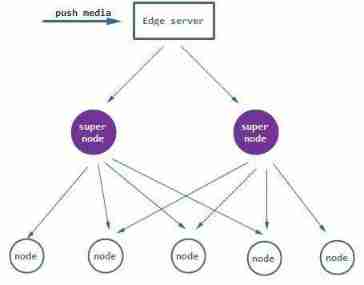
In the transmission and distribution network, we combine the wheat connection system with the distribution system , Distributed streaming and edge node distribution are regarded as a set of transmission system , Between services P2P Communication and routing to achieve the minimum delay of connecting wheat .
The structure is as follows :

The whole transmission and distribution network is divided into three parts :
Push flow part ;
Between services P2P;
Customer node P2P.
This transport network has a system anchor : Suppose the stream pusher speaker push to Edge server There will be no packet loss or delay ,Edge server Through the service room P2P Quickly distribute the received stream data to other Edge server, And there will be no delay and packet loss in this process .
Why do you need such an anchor ? Because at the customer node P2P The network needs to guarantee smoothness and minimum delay , That is to say, all Edge server Have complete data in the shortest time period , As for why , Later, we will focus on flow compensation .
I will analyze the specific technical details through the whole process of streaming data transmission , But before that, the first thing to be solved is the problem of media data fragmentation , All transmission processes will be based on fragmentation (segment) To design .
3.2 Media data fragmentation
Media data slicing is the most basic part of the entire distribution and transmission system , When we design the sharding, we mainly consider the delay and consumption , If the slice is too big , The higher the transmission delay , for example HLS; If the slice is too thin , There will be many feedback messages in the network , Yes P2P The extra cost of the network is also a problem .
Finally, we learn from RTP and FLV Experience in , Use frame by frame to do data segmentation , There are several advantages to doing so :
The delay granularity of frame fragmentation is small , Delay optimization can be carried out in frame transmission ;
Implement a simple , Consistent with the coding principle of codec ;
Flexible combination , It can play buffer Seamless combination .
Each fragment is called segment, With a self - increasing 32 position ID To show uniqueness , The transmission process is based on this ID To determine the integrity of data for labeling .
3.3 Push flow and connect wheat
Once the media partition is confirmed, streaming can be carried out , We combine the push stream with the distribution path , The listener will stream data segment Push to the nearest Edge server On , Instead of pushing it to a special wheat connection system . We use... For streaming RUDP Transmission algorithm , This RUDP Is similar to BBR Congestion algorithm based on delay and packet loss , And the packet is congestion discarded .
The schematic diagram is as follows :

About RUDP For more details, please refer to another article of mine 《 How to make unreliable UDP reliable ?》. As for why not RTP perhaps RTMP/TCP To push the flow , because RTP Although it is based on UDP Of , But it needs to go through RTCP and NACK To ensure reliability , Need to design congestion algorithm , You need to be right RTP Carry out transformation and expansion , But also by RTP Limitations of the agreement itself , So we didn't directly adopt RTP. Use RTMP/TCP It is very simple to design , But in the weak network environment, the delay is very large , And it is easy to cause reconnection , So at the beginning of the design, it also denied .
3.4 Server Between the P2P
Because the whole transmission and distribution network is distributed , By multiple Edge server form , So based on the system anchor , Media data slicing to Edge server Must be distributed to others as soon as possible Edge server On . In the early days, we used BGP server To transit , It costs BGP A lot of bandwidth , and BGP server Once abnormal , Whole Edge server The communication between them was interrupted .
In fact, most of the time, cross operator Edge server The delay is not as big as expected , This can be considered using Edge server Point-to-point communication to solve problems , So we designed a system based on RUDP Windowless multipath transmission model Edge server Communication between , Here's the picture :

The above communication model is a multi-path parallel communication model , We are RUDP A path routing table is added before sending , This routing table records the distribution probability of each path ,RUDP Each time a packet is sent to the receiving end, the path will be selected according to the probability in the routing table . So it is very important to determine the routing table probability . We go through RUDP real time ACK Feedback and path real time ping Probe to get the status of the network ( Packet loss 、 Delay 、 shake ), Then input the network state parameters into the approximation function f(x) To determine the probability of each route , Here is a principle : If Edge server When the delay and packet loss of direct connection are small enough , The probability of direct communication routing will be close to 100%, If a route is periodically disconnected or the delay exceeds 200ms, Its probability will be close to 0.
The following is the process diagram of the whole routing probability evaluation :

4、 be based on P2P Real time live video network construction process
The media stream data passes through Edge server Between the P2P The multi-path transmission network reaches each Edge server On , Next each Edge server The stream data needs to be distributed to each customer node in pieces , We have made special transmission processing for the uplink node to reduce the delay , Process and common RTC The communication model is similar , I won't repeat it here . The distribution on the watch node is self-organized P2P The Internet , Since it's through P2P Issued , Then we need to build a in the customer node group P2P The Internet , How this network is built ? There are three steps : Connect 、 assessment 、 layered .
4.1 Connect
The client node program runs on the client , Most of the client nodes will be in the router or NAT Back , They need to connect with each other , Must cross each other's NAT And the firewall . Although now through NAT There are many ways , Such as STUN、ICE etc. , But the traversal connectivity is always a problem , If the crossing rate is too low , Many high-quality node resources will not be fully utilized .
When designing the crossing scheme, we put the direct connection rate in the first place , By modifying the STUN The protocol designs a traversal mechanism based on multiple port guesses and attempts . First, through something like STUN Agreement judgment NAT type 、NAT Port change rule 、NAT Whether there is blacklist mechanism and other information , Then save this information to the... In the jurisdiction connection Edge server in , When a partner node comes to cross with it , Will exchange this information with each other , Different permutations have different crossing strategies , The process and results of each crossing will be recorded in our background database , We will periodically analyze these data and adjust the negotiation crossing strategy . Here's the picture :

After crossing , The connection handshake and identity certificate authentication will be carried out between nodes ( The reason for the certificate will be explained later ), Establish communication and neighborhoods . So how does the neighborhood relationship change dynamically ?
4.2 Neighborhood relations and evaluation
【 Neighbor problem 】:
Once the connection is complete , Nodes become neighbors with each other , Each other will exchange States and heartbeat , So here comes the question , A live broadcast system has thousands of nodes involved , If they are connected in pairs, the optical heartbeat communication can occupy the upload bandwidth of the client node . We designed a node LRU Eliminate the linked list , Keep in the linked list 40 Connected neighbor nodes , The old node will exit , New nodes will be added ,LRU It will be carried out according to the communication status between neighbors and themselves LRU Addition and elimination , The principles are as follows :
Nearby principle , Intranet is preferred , The same operator network in the same city takes the second place ;
Periodically evaluate latency and media fragmentation hit rate , Take out ;
When LRU There are not enough nodes in the list 40 A new node will be selected from the standby node list for connection and added to LRU in .
【 Node evaluation 】:
Computing power of each customer node 、 Communication capability and network partition are different , This makes us have to make an evaluation for each node , The evaluation of a node is divided into two parts : Neighbor nodes' evaluation of themselves and their own evaluation of themselves .
The neighbors' comments are mainly :
RTT;
Packet loss rate ;
Request hit rate .
Through these three parameters, an affinity score will be calculated for each neighbor score, This value will be used for subsequent distribution selections .
Mainly evaluate these points :
CPU、 Memory ;
Network type :WIFI/4G/ Wired network ;
Upload bandwidth .
Nodes periodically calculate these two types of parameters , Through a network QOS Convergence function f(x) To calculate node capacity and to neighbors QOS Strategy .
4.3 Node hierarchy
The ultimate goal of node evaluation is to make capable nodes become super nodes (super node) To share Edge server Distribution pressure .
What are the conditions for a node to become a super node ? There are the following conditions :
Enough upload bandwidth ,4G And weak WIFI The next node cannot be a supernode ;
There is something free CPU And memory , Low end mobile devices with insufficient computing power cannot become super nodes ;
Be friendly to neighbor communication , It is not a communication island ;
obtain Edge server Appointment of , and Edge server Smooth communication between .
What to do if the performance of the super node decays ? The answer is that it will degenerate into ordinary nodes , Because node evaluation is performed periodically and in real time , If node performance degradation is found ,Edge server Will make it degenerate .
Now that the super node has been appointed , So how does a super node work ? Each super node is assigned to a group when it is appointed ID,Edge server It will be grouped according to the number of super nodes in its jurisdiction , Each group consists of multiple supernodes , The super node in the packet bears the media partition distribution of its own packet . for example : Yes 5 Super node grouping , In this case, there are 1 ~ 20 individual segment, Then the first group is responsible for 1、6、11、16 Numbered segment distribution , By analogy, the second group is responsible for 2、7、12、17 …… This is done to prevent a single supernode from failing , Enhanced P2P Stability of distribution .
The schematic diagram is as follows :
5、 be based on P2P Real time live video streaming media distribution process
Through the top P2P We know the whole process of network construction P2P The network is actually a hierarchical directed graph distribution network , So how do you distribute streaming data ? There are also three steps : Push first (push)、 Pull back (pull)、 Recompense . Let's explain how it is implemented .
5.1 push
When introducing the super node, it is mentioned that it will be based on segment ID Push the data to the corresponding super node group , The supernode receives these segment How to deal with it after ? according to P2P The design principle should forward the data to the super node or ordinary node of other packets , But if you push like this, it may cause redundant network transmission and consume too much bandwidth .
To solve this problem, we designed a pre subscription mechanism , The principle is that every P2P The client node will determine the maximum buffer size according to its own buffer size segment ID To make a reservation , Book in advance 10 Media data fragmentation after seconds , The reservation request should be based on the affinity value evaluated by the node score Do weigh , The super node that receives these requests will save the subscribed partition request information , wait until Edge server Push the partition to the super node , It will unconditionally forward these subscribed packets to the node initiating the subscription , As shown in the figure below :

The following principles can be seen from the above figure :
from Edge server Up to two levels of paths to all nodes , This is done to control link delay ;
Different grouping super node They will subscribe to each other's corresponding groups segment;
Ordinary node Only to super node Initiate subscription .
5.2 pull
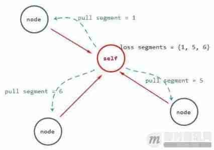
data segment Through pre subscription push Push to each customer node , But the network will lose packets ,super node It is also possible to quit halfway , This will cause packet loss in the final node , What shall we do if we lose the package ?
We design a mechanism to pull missing fragments from neighbors , The general process is as follows :
The node periodically checks the information of missing fragments and the information of received fragments , Construct a gossip The protocol exchanges buffer information to neighbors ;
A node receives a message from a neighbor gossip Information , Record the partition information owned by the other party to the local ;
Local users can find their lost partitions according to the partition information of their neighbors , By neighbor affinity value score Make a trade-off and randomly select neighbors , And to the selected neighbors pull request ;
Received a neighbor pull partition request , Send sharding to the requesting node .
The whole step will periodically try to pull many times , The schematic diagram is as follows :
It is worth mentioning here because buffers are periodically exchanged gossip Information , This means that the buffer gossip The smaller the information, the better , We designed a similar bloom filter To describe gossip Information , Can not only reduce gossip The data size of the message , And the comparison speed is very fast .
5.3 compensate
because P2P The client node of is unstable , It's possible that one segment After pulling for many times, I still haven't received , This segment And close to the playing position , So this is missing segment The node of the will be directed to Edge server Request compensation to send this partition as soon as possible , The purpose of this is to prevent P2P Packet loss caused by communication . This means that everyone Edge server Need to have all shard data , This is the anchor point of the system .
The flow is as follows: :

In most cases, this process is not a problem , But if most of the customer nodes are missing at the same time segment Fragmentation , There will be a large number of compensation requests to Edge server On , This will cause a network storm . We designed a scarcity assessment and denial of service mechanism to deal with this problem . This mechanism means that when too many compensation requests arrive in a unit time Edge server, So this Edge server Will refuse requests beyond their ability to bear , Only resend the fragments within the bearing range . And this process will also evaluate the scarcity of compensation requests , If most nodes in a partition do not , It will take the initiative to pass the partition super node Group push again .
5.4 buffer buffer And time delay control
Through the above three stages, all data can be segment Distribute to each customer node , But the client node needs a buffer buffer To match the three stages and local playback ,buffer If the buffer time is too long , It will cause unnecessary delay , If it is too short, it will cause the Caton and the three stages to be incomplete .
So we designed a three-stage buffer Dynamic buffer , As shown in the figure below :

Next, I will explain the meaning of each interval in the above figure :
push Section : Because slicing is through different super node Push it over , Then it will inevitably cause some jitter , So in buffer There will be one on the head at the beginning jitter Buffer stage , Until the first neighbor node gossip There is this fragment in the message push End of position , This phase generally lasts 100 ~ 300ms;
pull Section : The fragment sequence enters pull After the interval , The missing pieces will be checked periodically , according to gossip Master the neighbors to weigh and pull , Will be carried out in 3 Attempts to , The time of each attempt is between the local node and its neighbors RTT value .3 The second failure will enter the compensation interval ;
Compensation interval : After the slicing sequence enters the compensation interval , It will also periodically check for missing fragments , According to the missing pieces ID Direct to Edge server Request pull , Try 4 Time , Each attempt takes one local node and Edge server Between RTT. If 4 If you fail, go ahead waiting state , Waiting for neighbors gossip perhaps Edge server Take the initiative to push ;
Expiration interval : After being played, the tiles will be placed in the expired section instead of being deleted immediately , Why? ? Because the playback time of each node is different , It is possible that the fragments played locally are the fragments lost by other nodes , It is possible that other nodes will pass through pull To pull , Therefore, we will put the played fragments in the expired section 3 Delete in seconds .
5.5 Second open question
The three phases and buffer Control solves the problems of continuous stream distribution and playback delay control , However, at this stage, all live broadcast technologies must be enabled in seconds , Actually P2P Distribution is more effective than simple Server CDN Forwarding should be simpler . Seconds on means that users can instantly see the video image of the anchor when they enter the live room , The purpose of seckai is that the newly entered client node requires the server edge node to start from the previous video GOP Key frame starts sending data , The client node then receives the video from the video encoder GOP Key frame zero wait for accelerated playback . We are P2P New nodes in the distribution network will receive Edge server The last one of GOP Key frame fragmentation ID, The customer node is based on this ID Quickly pull the whole... From each neighbor GOP Fragmentation data , Instead of simply letting Edge server Come on , The average speed of the second switch is shortened 100 millisecond .
6、 be based on P2P Real time live video content authorization
In addition to transmission and distribution, live broadcast distribution technology , Content theft prevention and authorization also need to be considered ,P2P System security needs to be considered in the system . We introduced CA The certificate and the two sides negotiate the encryption scheme to ensure the legitimacy of the link . The general approach is that each legal node unit (Edge server And all customer nodes ) Will send to CA Initiate legal verification , If the test passes ,CA According to the node ID、 node RSA Public key 、 Authorization start time, authorization end time and other information are used CA Of RSA Generate certificate . Each node unit that gets the certificate needs to communicate with other nodes , Exchange certificates first , Verify the validity of the other party's certificate , Then use the certificate RSA Public key encryption algorithm KEY Return to the certifier , The certificate party received an encrypted KEY Can be used later RSA Private key decryption results in symmetric encryption KEY, In this way, both parties complete the legitimacy verification and use the exchange KEY Conduct message encryption and decryption communication .
The flow is as follows: :

7、 Online data comparison
The above technical analysis only helps readers understand the operation mechanism of the system , in addition to , Of course, it is necessary to publish an offline data to prove the feasibility of the system , Here is a 10W+ The online live broadcast platform uses this P2P Comparison data on the back line of the system . We are in the same Edge server In the same live studio object on , Turn off half of the user nodes P2P, Half of the users turn on P2P, To observe the same in a day Edge server The bandwidth consumption of these two user groups .

As can be seen from the above figure ,P2P The mode bandwidth consumption is only disabled P2P Mode 1/4, We are P2P The system saves 75% The cost of bandwidth . The video sample of this data is single channel 480P 800kps Rate live stream , The number of real nodes in peak period 1000+, Finally, the average delay of all terminals is 1.07 second .
8、 This paper summarizes
To go here about P2P The technical analysis of the distribution network is over ,P2P Technology has experienced from its birth to the present 19 year , and P2P CDN It's the next generation CDN The main technology of ,P2P Technology and models have been changing and improving . We use in live broadcast distribution UDP and P2P It is to solve the problem of interaction between our educational scenes from the perspective of cost and delay , The starting point is different , You will get different results , If you have trouble with costs and delays , Try this technique to solve the problem .
appendix : More real-time audio and video technology articles
[1] Open source real-time audio and video technology WebRTC The article :
《 Open source real-time audio and video technology WebRTC The status quo of 》
《 Open source real-time audio and video technology WebRTC Advantages and disadvantages 》
《 interview WebRTC Father of standards :WebRTC Past 、 Present and future 》
《 Conscience sharing :WebRTC Zero basic developer tutorial ( chinese )[ Download the attachment ]》
《 WebRTC Introduction to the overall architecture of real-time audio and video technology 》
《 getting started : What exactly is WebRTC The server , And how it connects ?》
《 WebRTC Fundamentals of real-time audio and video technology : Basic architecture and protocol stack 》
《 Technical points of developing live video platform 》
《 [ Point of view ] WebRTC You should choose H.264 Four reasons for video coding 》
《 Based on open source WebRTC Is the development of real-time audio and video reliable ? The first 3 Fang SDK What are they? ?》
《 Open source real-time audio and video technology WebRTC in RTP/RTCP Application of data transmission protocol 》
《 End to end encryption in real-time audio and video chat (E2EE) How it works 》
《 real-time communication RTC Technology stack : Video codec 》
《 Open source real-time audio and video technology WebRTC stay Windows The next concise compilation tutorial 》
《 Real time audio and video technology on Web WebRTC: It looks beautiful , But how many pits still need to be filled before production and Application ?》
>> More articles of the same kind ……
[2] Other essential information for real-time audio and video development :
《 Interview with the technical director of wechat video : The evolution of wechat real-time video chat Technology 》
《 Audio and video development of instant messaging ( One ): The theory of video codec 》
《 Audio and video development of instant messaging ( Two ): Digital video introduction of video coding and decoding 》
《 Audio and video development of instant messaging ( 3、 ... and ): Coding basis of video coding and decoding 》
《 Audio and video development of instant messaging ( Four ): Prediction technology of video codec 》
《 Audio and video development of instant messaging ( 5、 ... and ): Understanding the mainstream video coding technology H.264》
《 Audio and video development of instant messaging ( 6、 ... and ): How to start learning audio codec technology 》
《 Audio and video development of instant messaging ( 7、 ... and ): Introduction to audio fundamentals and coding principles 》
《 Audio and video development of instant messaging ( 8、 ... and ): Common real-time voice communication coding standards 》
《 Audio and video development of instant messaging ( Nine ): Echo and echo cancellation of real-time voice communication � summary 》
《 Audio and video development of instant messaging ( Ten ): Echo cancellation in real-time voice communication � Technical details 》
《 Audio and video development of instant messaging ( 11、 ... and ): Detailed explanation of packet loss compensation technology in real-time voice communication 》
《 Audio and video development of instant messaging ( Twelve ): Discussion on the framework of real-time audio and video chat for multiple people 》
《 Audio and video development of instant messaging ( 13、 ... and ): Real time video coding H.264 Characteristics and advantages of 》
《 Audio and video development of instant messaging ( fourteen ): Real time audio and video data transmission protocol 》
《 Audio and video development of instant messaging ( 15、 ... and ): Chat P2P And real-time audio and video applications 》
《 Audio and video development of instant messaging ( sixteen ): Some suggestions on the development of real-time audio and video in mobile terminal 》
《 Audio and video development of instant messaging ( seventeen ): Video coding H.264、VP8 The past and this life 》
《 Audio processing and coding compression technology in real-time voice chat 》
《 Netease video cloud technology sharing : Audio processing and compression technology quick start 》
《 Study RFC3550:RTP/RTCP Basic knowledge of RTP 》
《 be based on RTMP Research on real-time streaming media technology of data transmission protocol ( Paper full text )》
《 Voice network architects talk about the difficulties of real-time audio and video cloud ( Video interview )》
《 Technical points of developing live video platform 》
《 Still on “ Hello, hello. ” Test real-time voice call quality ? This article will teach you scientific evaluation methods !》
《 Implementation delay is less than 500 ms 1080P Practice sharing of real-time audio and video live broadcasting 》
《 Practice of real-time live video technology on mobile terminal : How to turn on in real time 、 Fluency without cards 》
《 How to test your real-time audio and video scheme in the simplest way 》
《 Technical disclosure : Supporting the interaction of millions of fans Facebook Live video 》
《 End to end encryption in real-time audio and video chat (E2EE) How it works 》
《 Detailed explanation of real-time audio and video live broadcast technology in mobile terminal ( One ): The opening 》
《 Detailed explanation of real-time audio and video live broadcast technology in mobile terminal ( Two ): collection 》
《 Detailed explanation of real-time audio and video live broadcast technology in mobile terminal ( 3、 ... and ): Handle 》
《 Detailed explanation of real-time audio and video live broadcast technology in mobile terminal ( Four ): Coding and encapsulation 》
《 Detailed explanation of real-time audio and video live broadcast technology in mobile terminal ( 5、 ... and ): Streaming and transmission 》
《 Detailed explanation of real-time audio and video live broadcast technology in mobile terminal ( 6、 ... and ): Delay optimization 》
《 Combining theory with practice : Realize a simple foundation in HTML5 Live video of 》
《 IM Detailed explanation of echo cancellation technology in real-time audio and video chat 》
《 Several key technical indicators that directly affect user experience in real-time audio and video live broadcast 》
《 How to optimize the transmission mechanism to realize the ultra-low delay of real-time audio and video ?》
《 First disclosure : How can Kwai do millions of viewers live in the same field and still live in seconds? ?》
《 Android Introduction to live broadcasting : Build a simple live broadcast system 》
《 Netease cloud real time video live in TCP Some optimization ideas of data transmission layer 》
《 Real time audio and video chat technology sharing : Anti loss codec for unreliable network 》
《 P2P How to reduce the bandwidth of live video 75%?》
>> More articles of the same kind ……
( This article is published synchronously in :http://www.52im.net/thread-1289-1-1.html)
边栏推荐
- 瀚高数据库自定义操作符‘!~~‘
- Apktool tool usage document
- 《财富自由之路》读书之一点体会
- SSH connected to win10 and reported an error: permission denied (publickey, keyboard interactive)
- 超高精度定位系统中的UWB是什么
- ssh连win10报错:Permission denied (publickey,keyboard-interactive).
- Difference between return and yield
- Final review of brain and cognitive science
- [ide (imagebed)]picgo+typora+aliyunoss deployment blog Gallery (2022.6)
- Interpretation of yolov5 training results
猜你喜欢
Technical past: tcp/ip protocol that has changed the world (precious pictures, caution for mobile phones)

A company crawling out of its grave

Yolov5 super parameter setting and data enhancement analysis
![[unity3d] human computer interaction input](/img/4d/47f6d40bb82400fe9c6d624c8892f7.png)
[unity3d] human computer interaction input

torchvision_ Transform (image enhancement)

Classic theory: detailed explanation of three handshakes and four waves of TCP protocol
![[unity3d] rigid body component](/img/57/344aae65e4ac6a7d44b235584f95d1.png)
[unity3d] rigid body component

Pycharm package import error without warning

5. <tag-栈和常规问题>补充: lt.946. 验证栈序列(同剑指 Offer 31. 栈的压入、弹出序列)

创建 SSH 秘钥对 配置步骤

随机推荐
Cookie and session Basics
ThreadPoolExecutor实现文件上传批量插入数据
Tp5.0 framework PDO connection MySQL error: too many connections solution
How to rewrite a pseudo static URL created by zenpart
[geek] product manager training camp
Lstms in tensorflow_ Cell actual combat
微服务之间的Token传递之一@Feign的token传递
Sentimentin tensorflow_ analysis_ layer
date_ Range creation date range freq parameter value table and creation example
两步处理字符串正则匹配得到JSON列表
Illustration of ONEFLOW's learning rate adjustment strategy
Codeforces Round #802 (Div. 2)(A-D)
Anaconda creates tensorflow environment
C# 39. Conversion between string type and byte[] type (actual measurement)
Zhongshanshan: engineers after being blasted will take off | ONEFLOW u
Learn from small samples and run to the sea of stars
Ai+ remote sensing: releasing the value of each pixel
Modify the case of the string title(), upper(), lower()
Technical past: tcp/ip protocol that has changed the world (precious pictures, caution for mobile phones)
[unity3d] collider assembly