当前位置:网站首页>51 single chip microcomputer multi computer communication
51 single chip microcomputer multi computer communication
2022-06-25 01:02:00 【xuechanba】
Video learning link : https://www.bilibili.com/video/BV1pi4y147A6?spm_id_from=333.880.my_history.page.click&vd_source=b91967c499b23106586d7aa35af46413


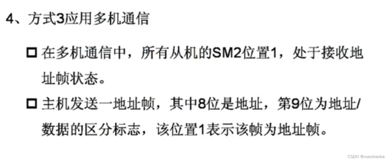
Only used in case of multi computer communication SM2 , In general, do not use .

TB8 It is used when sending data , And RB8 Corresponding .


The ninth digit of the data is the check digit .
The difference between serial mode 2 and mode 3 is , The baud rate of serial mode 2 is fixed , There are only two options , The baud rate of mode 3 is determined by the timer T1 Is determined by the overflow rate , That is, mode 3 is a working mode with variable baud rate .
therefore , When working in mode 3 , First, understand the communication sequence of mode 3 ,


When other events are handled between processes , If there is an interruption , Execute the corresponding interrupt program .


Each time the host key is pressed , Add... To the count result 1 , At the same time, the counting result is displayed on the nixie tube . And when the switch is grounded , Send to 1 Single chip microcomputer No . When the switch is connected to high level , Send to 2 Single chip microcomputer No . After each slave receives the data, it should display the receiving result on its own digital tube .


After sending the slave address , Or during key counting , Interrupt requests may occur .
If RB8 The value of is 1 Words , Is the address signal , If RB8 The value of is 0 Words , Data signals .
Finally, the program code and simulation are uploaded to the data file .
边栏推荐
- Leetcode 1248. 统计「优美子数组」(害,突然发现只会暴力枚举了)
- 腾讯云国际云服务器网络访问丢包问题解决办法
- Unimportant tokens can be stopped in advance! NVIDIA proposes an efficient visual transformer network a-vit with adaptive token to improve the throughput of the model
- EVM简略
- 2021-02-15
- Helm chart仓库操作
- Some examples of MgO operating database in go
- Alternative to log4j
- [microservices sentinel] cluster link | microservices cluster environment construction
- Use of navigation and navigationui
猜你喜欢

The acceleration of 100 km is only 5.92 seconds, and the willanda high-performance version leads with the strength of high-energy products

Virtual machine - network configuration

Apk slimming compression experience

2022年危险化学品经营单位安全管理人员考试试题及模拟考试

Go crawler framework -colly actual combat (III) -- panoramic cartoon picture capture and download
@mysql
[distributed system design profile (2)] kV raft

Wallpaper applet wechat applet

傳輸層 以字節為單比特的滑動窗口技術

Usage of ViewModel and livedata in jetpack

随机推荐
Technologie des fenêtres coulissantes en octets dans la couche de transmission
In the process of enterprise development, I found that a colleague used the select * from where condition for update
C# 闭包的垃圾回收
Thingsboard - rest API obtains and refreshes tokens
Use of JMeter easynmon
Thermodynamic diagram display correlation matrix
我想问一下兴业证券怎么开户?通过链接办理股票开户安全吗
Tiktok wallpaper applet source code
Eliminate duplicate dependencies
Tiktok wallpaper applet v1.0.2 function, new arrival function
2021-11-05
Applet opening traffic master
【Redis实现秒杀业务④】一人一单,不可重复购买
Helm chart仓库操作
More pictures | explain the Nacos parameters in detail!
Databinding quick start (still using findviewbyid?)
2022熔化焊接与热切割复训题库模拟考试平台操作
108页(4万字)未来公寓智能化设计平台项目方案建议书2022版
How to reduce the font size of custom controls (optimize the round dot progress bar)
Custom animation (simulated win10 loading animation) - Optimization