当前位置:网站首页>Digital ic-1.9 understands the coding routine of state machine in communication protocol
Digital ic-1.9 understands the coding routine of state machine in communication protocol
2022-06-27 08:37:00 【EMB night watching lights】
Catalog
- One 、 Preface
- Two 、 Example preparation knowledge
- 3、 ... and 、 Time series method WE Command code example
- Four 、 Logical method BE Command code example
- 5、 ... and 、 Test the source code file
- 6、 ... and 、 Thoughts and questions about the writing of general instruction set state machine
- 7、 ... and 、 A small example of block command framework design ( The problem of mixing two methods and verifying six )
One 、 Preface
This paper aims at verilog HDL When writing different communication protocols in , It is necessary to discuss the code implementation methods of different command state machines . The author's level is limited , Please also correct .
The article uses SPI Protocol pair flash Send a full erase instruction as an example , Discuss the advantages and disadvantages of the following two different writing methods and the specific implementation methods :1、 utilize always The statement block method obtains the state jump condition or time waiting flag for protocol port output ( Hereinafter referred to as “ Logical method ”);2、 Use cnt Counter , The drive clock frequency is at least spi_clk On the premise that the clock frequency is more than twice , The writing method of describing the behavior at different times of time sequence ( Hereinafter referred to as “ Time series method ”).
The conclusion of the comparison between the two :
Logical method : advantage - It is more convenient to customize and modify in subsequent projects , The protocol communication description logic is more clear and specific , It can more abstractly and regularly describe the behavior of protocol communication . shortcoming - It is more complicated to write jump restriction logic design between different protocol behaviors , There are many code emulation adjustments , It is necessary to repeatedly consider the delay between different registers to free up the delay margin in advance , Meet the requirements of efficient and compact timing .( characteristic : Small blocks of sequential logic are more , Simpler cabling , Smaller area , It's a little slow )
Time series method : advantage - Writing new ideas is simple and clear , Fast development speed , Can be easily and effectively located to bug Place of existence , Efficient code execution . shortcoming - There are many places where other functions can be customized in the later stage , It is not easy to understand the law of jump between time series , It can not objectively describe the relationship between the changes of protocol behavior sequence .( characteristic : Fewer blocks , But a case There are many progressive judgment conditions for the internal counter , The wiring is concentrated , So it's more complicated , Large area , Faster )
Use advice : Logical method is more suitable for given fixed length , Fixed format , A short command a short command a protocol that sends a command or receives a status . For the protocol with nonstationary continuous trigger or the protocol with very complex time sequence change of communication line in a command , It is recommended to use the time sequence method for writing . But in practical engineering application , In fact, there is no clear dividing line between them , It is usually used in combination with , The blogger's chicken and vegetable experience is , If the continuous signal is strongly coupled and there is a state jump during the duration of the signal, use the logic method , If the continuous signal only exists in one state and the change of multi line signal is complex, use the time sequence method .
Two 、 Example preparation knowledge
This paper makes use of spi Deal with the flash The chip communicates , Send it a full sector erase instruction . The instruction consists of two parts , One is to write the enabling part WE, One is the full erase command BE part . The sequence diagram is as follows .
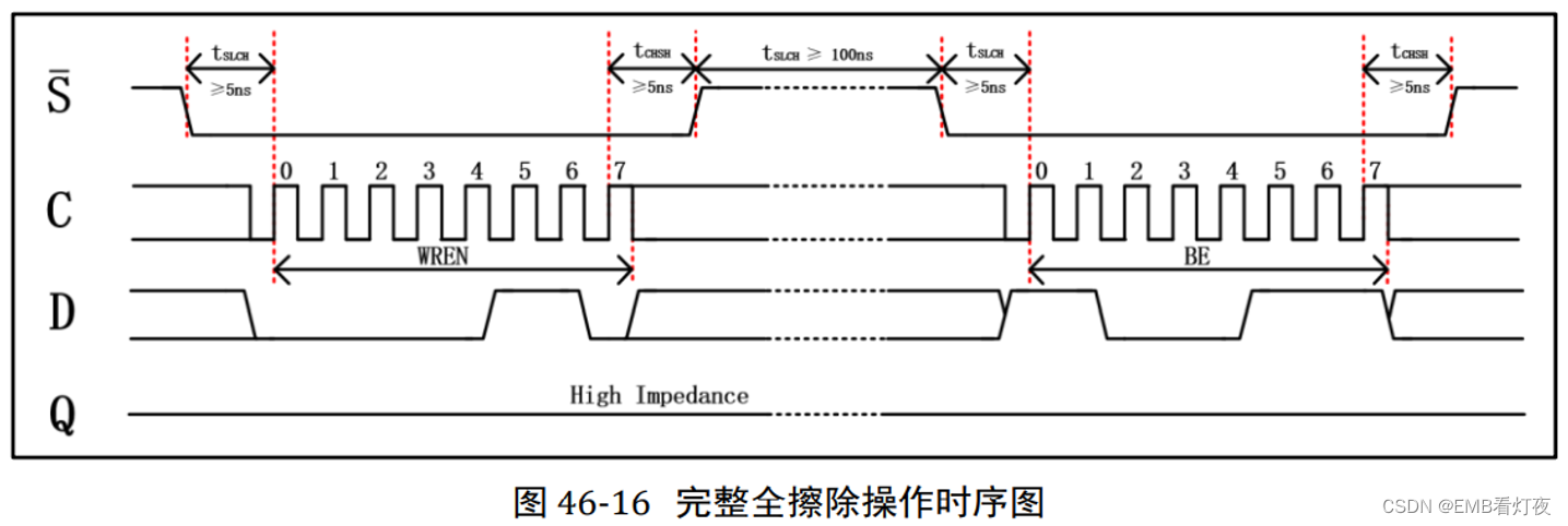
This article will use hardware presentation language , Two methods are used to describe the above timing . among WE Write enable (8'h06) It is realized by time sequence method ,BE Full erase (8'hc7) It is realized by logical method .
3、 ... and 、 Time series method WE Command code example
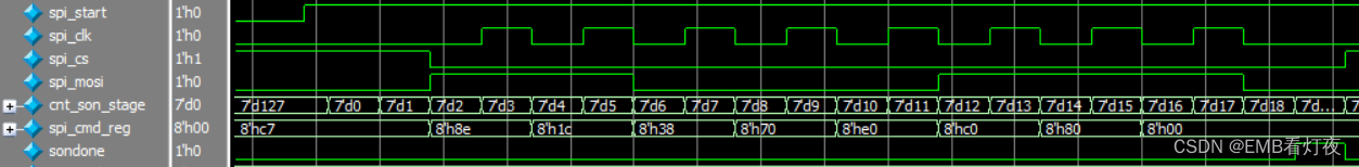
sequential

 As can be seen from the picture above , When spi_clk When it is the rising edge, the slave will pass mosi Sample the data , Therefore, in the low-level period between the rising edges, the command data to be issued should be placed in mosi Online ( This is because the nonblocking assignment of combinatorial logic delays one clock cycle ).
Be careful : here spi_cmd_reg The order of 8'n06 It is the same. , This is due to the command in the following code Direct addressing send It is decided by the compilation method of .
Source code
The time sequence method passed case Statement at every moment spi Each data line of the protocol acts as a jump for direct control , It makes this method simple and effective . Efficient code execution , There is no need to design mutually acceptable change triggering conditions between different data lines . But this method is not objective enough for people to read .
w_en_100ns : begin
                    case(cnt_son_stage)
                        7'd0 : begin
                            spi_cs  <= 1'b0;
                            spi_clk <= 1'b0;
                            spi_mosi    <= spi_cmd_reg[7];
                        end
                        7'd1 : spi_clk <= 1'b1;
                        7'd2 : begin
                            spi_clk  <= 1'b0;
                            spi_mosi <= spi_cmd_reg[6];
                        end
                        7'd3 : spi_clk <= 1'b1;
                        7'd4 : begin
                            spi_clk  <= 1'b0;
                            spi_mosi <= spi_cmd_reg[5];
                        end
                        7'd5 : spi_clk <= 1'b1;
                        7'd6 : begin
                            spi_clk  <= 1'b0;
                            spi_mosi <= spi_cmd_reg[4];
                        end
                        7'd7 : spi_clk <= 1'b1;
                        7'd8 : begin
                            spi_clk  <= 1'b0;
                            spi_mosi <= spi_cmd_reg[3];
                        end
                        7'd9 : spi_clk <= 1'b1;
                        7'd10 : begin
                            spi_clk  <= 1'b0;
                            spi_mosi <= spi_cmd_reg[2];
                        end
                        7'd11: spi_clk <= 1'b1;
                        7'd12: begin
                            spi_clk  <= 1'b0;
                            spi_mosi <= spi_cmd_reg[1];
                        end
                        7'd13: spi_clk <= 1'b1;
                        7'd14: begin
                            spi_clk  <= 1'b0;
                            spi_mosi <= spi_cmd_reg[0];
                        end
                        7'd15: spi_clk <= 1'b1;
                        7'd16: begin
                            spi_clk  <= 1'b0;
                            spi_mosi <= spi_cmd_reg[0];
                        end
                        7'd17: begin
                            spi_cs        <= 1'b1;
                            spi_mosi      <= 1'b0;
                        end
                        7'd20: begin
                            cnt_son_stage <= 7'd127;
                            sondone       <= 1'b1;
                        end
                        default: ;
                    endcase
                end
Four 、 Logical method BE Command code example
sequential
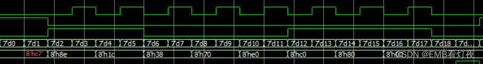 As can be seen from the picture above , When spi_clk When it is the rising edge, the slave will pass mosi Sample the data , Therefore, in the low-level period between the rising edges, the command data to be issued should be placed in mosi Online ( This is because the nonblocking assignment of combinatorial logic delays one clock cycle ).
Be careful : here spi_cmd_reg The order of 8'nca It's a change , This is because the command in the following code is through High order shift cyclic address transmission It is decided by the compilation method of .
Source code
The logical method passes through a few if Conditional judgment statements indirectly trigger and manipulate the behavior of time sequence , Making this method written not only needs to analyze and write what different time segment protocols should do , It is also necessary to analyze the triggering relationship between different signal lines in each time period . The code describes the law of signal change objectively and easily , It is helpful for later revision and personnel reading .
cmd_cyc : begin
                        if(cnt_son_stage == 7'd20) begin //  complete
                            sondone       <= 1'b1;
                            cnt_son_stage <= 7'd127;
                        end
                        else if(cnt_son_stage == 7'd1) begin
                            spi_cs      <= 1'b0;
                            spi_clk     <= 1'b0;
                            spi_mosi    <= spi_cmd_reg[7];
                            spi_cmd_reg <= {spi_cmd_reg[6:0],1'b0};
                        end
                        else if(cnt_son_stage > 7'd1 && cnt_son_stage < 7'd18) begin
                                spi_clk  <= ~spi_clk;
                            if(spi_clk) begin
                                spi_mosi    <= spi_cmd_reg[7];
                                spi_cmd_reg <= {spi_cmd_reg[6:0],1'b0};
                            end
                            else begin
                                spi_mosi    <= spi_mosi   ;
                                spi_cmd_reg <= spi_cmd_reg;
                            end
                        end
                        else  begin
                            spi_cs        <= 1'b1 ;
                            spi_cmd_reg   <= spi_cmd_reg;
                            spi_mosi      <= 1'b0;
                            spi_clk       <= 1'b0;
                        end
                end
5、 ... and 、 Test the source code file
`timescale 1ns/1ns
`define WEL_CMD 8'h06 // Write enabling commands
`define C_ERA_CMD 8'hc7 // Erase all command
module tb_test();
reg sys_clk ; // Analog clock signal
reg sys_rst_n ; // Analog reset signal
reg spi_start ;//spi Turn on the enable .
reg spi_cs ;//SPI The chip selection signal of the slave , Low level active .
reg spi_clk ;// Data synchronization clock between master and slave .
reg spi_mosi ;// Data pins , Host output , Slave input .
reg [ 7:0] spi_cmd ;
reg [ 2:0] cnt_stage ;
reg [ 6:0] cnt_son_stage ;
reg [ 7:0] spi_cmd_reg ;//FLAH Operating instructions
initial begin
sys_clk = 1'b1;
sys_rst_n <= 1'b0;
spi_start <= 1'b0;
#100
sys_rst_n <= 1'b1;
#300
spi_start <= 1'b1;
//spi_addr_reg <= ;//FLASH Address
#(20*47)
spi_start <= 1'b0;
#300
spi_start <= 1'b1;
//spi_addr_reg <= ;//FLASH Address
#(20*47)
spi_start <= 1'b0;
#600
$stop();
end
always # 10 sys_clk <= ~sys_clk; // 50M hz
reg clk_25M; // Read clock max 20MHZ, Here, the frequency will be reduced to... In the state machine 12.5Mhz
wire clk_drive;
reg spi_start_reg;
// The clock
always @(posedge sys_clk or negedge sys_rst_n ) begin
if(!sys_rst_n)
clk_25M <= 1'b0;
else
clk_25M <= ~clk_25M;
end
assign clk_drive = clk_25M;
[email protected](posedge clk_drive or negedge sys_rst_n) begin
if(!sys_rst_n) begin
spi_start_reg <= 1'b0;
end
else
spi_start_reg <= spi_start;
end
[email protected](posedge clk_drive or negedge sys_rst_n) begin
if(!sys_rst_n) begin
spi_cmd <= 8'b0;
end
else if(spi_start && !spi_start_reg)
if( spi_cmd == 8'b0)
spi_cmd <= 8'hc7;
//else if ( spi_cmd == 8'h06)
// spi_cmd <= 8'hc7;
else
spi_cmd <= spi_cmd;
end
// State machine state
localparam IDLE = 7'b000_0001;// Idle state
localparam WEL = 7'b000_0010;// Write enable status
localparam C_ERA = 7'b000_1000;// Global erase
// Command output status
localparam idle_stage = 8'b0000_0001,
w_en_100ns = 8'b0000_0010,
cmd_cyc = 8'b0000_0100,
adds_cyc = 8'b0000_1000,
end_6ns = 8'b0001_0000,
w_n_bit = 8'b0010_0000,
r_n_bit = 8'b0100_0000,
busy_8b = 8'b1000_0000;
reg [7:0] cur_stage ; // At this stage
reg stdone ; // Command completion flag
reg sondone ; // Subcommand phase completion flag
reg [6:0] cur_state ; // State machine current state
reg [6:0] next_state; // State machine next state
//( Three stage state machine ) Synchronous timing describes state transitions
always @(posedge clk_drive or negedge sys_rst_n) begin
if(!sys_rst_n)
cur_state <= IDLE;
else
cur_state <= next_state;
end
[email protected](*) begin
next_state = IDLE;
case(cur_state)
IDLE : begin
if(spi_start && spi_cmd == `WEL_CMD)
next_state = WEL;
else if(spi_start && spi_cmd == `S_ERA_CMD)
next_state = S_ERA;
else
next_state=IDLE;
end
WEL: begin
if(stdone)
next_state = IDLE;
else
next_state = WEL;
end
C_ERA: begin
if(stdone)
next_state = IDLE;
else
next_state = C_ERA;
end
default: next_state=IDLE;
endcase
end
[email protected](posedge clk_drive or negedge sys_rst_n) begin
if(!sys_rst_n) begin
spi_cs <= 1'b1 ;
spi_clk <= 1'b0 ;
spi_mosi <= 1'b0 ;
spi_cmd_reg <= 8'b0 ;
cur_stage <= idle_stage;
cnt_stage <= 3'b0;
cnt_son_stage <= 7'b0;
sondone <= 1'b0;
stdone <= 1'b0;
end
else begin
cur_stage <= idle_stage;
stdone <= 1'b0;
if(sondone) begin
cnt_stage <= cnt_stage + 1'b1;
sondone <= 1'b0;
end
else begin
cnt_stage <= cnt_stage;
sondone <= sondone;
end
case(cur_state)
IDLE : begin
cur_stage <= idle_stage;
cnt_stage <= 3'b0;
spi_cs <= 1'b1;
end
WEL: begin
case(cnt_stage) // mosi
3'd0 : begin
cur_stage <= w_en_100ns;
if(cnt_son_stage == 7'd1)
spi_cmd_reg <= `WEL_CMD ;
else
spi_cmd_reg <= spi_cmd_reg;
end
3'd1 : begin
stdone <= 1'b1;
cnt_stage <= 3'd2;
end
default: ;
endcase
end
C_ERA : begin
case(cnt_stage) // mosi
3'd0 : begin
cur_stage <= w_en_100ns;
if(spi_cs)
spi_cmd_reg <= `WEL_CMD ;
else
spi_cmd_reg <= spi_cmd_reg;
end
3'd1 : begin
cur_stage <= cmd_cyc;
if(spi_cs)
spi_cmd_reg <= `C_ERA_CMD ;
else
spi_cmd_reg <= spi_cmd_reg;
end
3'd2 : cur_stage <= end_6ns;
3'd3 : begin
stdone <= 1'b1;
cnt_stage <= 3'd4;
end
default: ;
endcase
end
default: ;
endcase
if(spi_start || cnt_son_stage != 7'd127)
cnt_son_stage <= cnt_son_stage + 1'b1;
else
cnt_son_stage <= cnt_son_stage;
case(cur_stage)
idle_stage : begin
spi_clk <= 1'b0;
spi_mosi <= 1'b0;
cnt_son_stage <= 7'b0;
end
w_en_100ns : begin
case(cnt_son_stage)
7'd0 : begin
spi_cs <= 1'b0;
spi_clk <= 1'b0;
spi_mosi <= spi_cmd_reg[7];
end
7'd1 : spi_clk <= 1'b1;
7'd2 : begin
spi_clk <= 1'b0;
spi_mosi <= spi_cmd_reg[6];
end
7'd3 : spi_clk <= 1'b1;
7'd4 : begin
spi_clk <= 1'b0;
spi_mosi <= spi_cmd_reg[5];
end
7'd5 : spi_clk <= 1'b1;
7'd6 : begin
spi_clk <= 1'b0;
spi_mosi <= spi_cmd_reg[4];
end
7'd7 : spi_clk <= 1'b1;
7'd8 : begin
spi_clk <= 1'b0;
spi_mosi <= spi_cmd_reg[3];
end
7'd9 : spi_clk <= 1'b1;
7'd10 : begin
spi_clk <= 1'b0;
spi_mosi <= spi_cmd_reg[2];
end
7'd11: spi_clk <= 1'b1;
7'd12: begin
spi_clk <= 1'b0;
spi_mosi <= spi_cmd_reg[1];
end
7'd13: spi_clk <= 1'b1;
7'd14: begin
spi_clk <= 1'b0;
spi_mosi <= spi_cmd_reg[0];
end
7'd15: spi_clk <= 1'b1;
7'd16: begin
spi_clk <= 1'b0;
spi_mosi <= spi_cmd_reg[0];
end
7'd17: begin
spi_cs <= 1'b1;
spi_mosi <= 1'b0;
end
7'd20: begin
cnt_son_stage <= 7'd127;
sondone <= 1'b1;
end
default: ;
endcase
end
cmd_cyc : begin
if(cnt_son_stage == 7'd18) begin // complete
sondone <= 1'b1;
cnt_son_stage <= 7'd127;
end
else if(cnt_son_stage == 7'd1) begin
spi_cs <= 1'b0;
spi_clk <= 1'b0;
spi_mosi <= spi_cmd_reg[7];
spi_cmd_reg <= {spi_cmd_reg[6:0],1'b0};
end
else if(cnt_son_stage > 7'd1 && cnt_son_stage < 7'd18) begin
spi_clk <= ~spi_clk;
if(spi_clk) begin
spi_mosi <= spi_cmd_reg[7];
spi_cmd_reg <= {spi_cmd_reg[6:0],1'b0};
end
else begin
spi_mosi <= spi_mosi ;
spi_cmd_reg <= spi_cmd_reg;
end
end
else begin
spi_cs <= 1'b1 ;
spi_cmd_reg <= spi_cmd_reg;
spi_mosi <= 1'b0;
spi_clk <= 1'b0;
end
end
end_6ns : begin
if(cnt_son_stage == 7'd6) begin // complete
sondone <= 1'b1;
cnt_son_stage <= 7'd127;
end
else begin
spi_cs <= 1'b1 ;
spi_cmd_reg <= 8'b0;
spi_mosi <= 1'b0;
spi_clk <= 1'b0;
end
end
default: ;
endcase
end
end
endmodule6、 ... and 、 Thoughts and questions about the writing of general instruction set state machine
I usually write communication protocols to communicate with devices , There will be such a problem . When the project uses a small number of commands , We can directly describe each command using the sequential method , And design state machine jump to realize . But when a project uses a large number of commands , If it is handled like the above method , There will be a lot of code redundancy and register resource waste , So in this case, what method is more appropriate to write ?
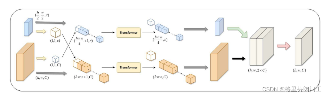
I believe that readers have their own answers in their hearts , I hope you can give me more advice in the comment area . The author learns ic Soon , Put forward your immature ideas . As above test bench The structure shown by the source code , I try to divide different commands into smaller common blocks , Then implement these small pieces , Different commands can be implemented as long as they are combined in order according to their own needs . Is it possible to achieve multi command compatibility ? It should be feasible in theory .


As shown in the above figure, the full erase command and the sector erase command , In fact, they can be disassembled into several different general-purpose pieces :1、 Write enable and what follows it 100ns Time delay .2、5ns Beginning and 8 individual spi_clk Command sending phase of the cycle .3、 Device operation address 24 Bit width address output stage .4、 Last 5ns End of data completion phase . Using the above four small blocks can be combined into two different operation instructions . If there is anything improper , Please make more corrections .
7、 ... and 、 A small example of block command framework design ( The conjecture that two methods are mixed and six methods are verified )
In response to the above ideas , I have carried out practical experiments . Verified part of my conjecture , At the same time, some thoughts have been gained .
Direct conclusions and examples !
analysis : The above idea of forming different large commands by dividing small and fast commands is feasible , It can make people see or write code more robust , But it also pays a price , That is, the power consumption increases as the number of state jumps increases ( The number of States increases )、 Need to design out of the combinational circuit To realize real-time jump of state according to different conditions , Although the area is increased, it is much smaller than the specific implementation of each command .
summary : This framework can shorten the development time , Reduce code maintenance costs , Reduce the occupied area , But it will increase power consumption and wiring difficulty . In addition, the hardware power consumption and speed cost in chip design are far greater than the labor cost and area cost , Therefore, the practical significance of this framework in practical engineering is not strong .
New conjecture : Is there any code with high readability and maintainability , The design method of protocol command state machine with low power consumption and high speed ? In fact, we can achieve this goal by introducing standardized code writing formats and writing more comprehensive unified function libraries . We can even set up some script files , Taking advantage of script files to give consideration to the readability and maintainability of code , The script file is used to automatically splice the real hardware description code with small sequential logic structure to give consideration to power consumption and efficiency , Finally, it can be adjusted manually in a small range .
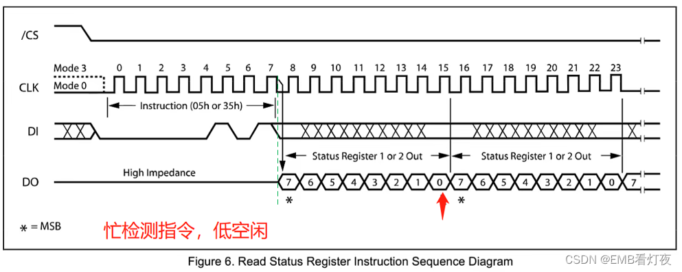
Preliminary knowledge : In the above implementation spi Of flash Full erase instruction C_ERA_CMD This is the picture 46-16 when , In fact, we need a command R_STA_REG_CMD To wait for the slave miso Line return flash Has been erased , So that the host knows when to start sending the next command . Once we will base on a complete flash Full erase process implementation example , Write enable WREN -》 Sector full erase RE -》 Wait for the query register to be selected 05h -》 wait for miso Every... On the line 8 The lowest bit of the bit is b[0]=0 when , The full data erasure process is over .
1.

2.
Sequence diagram :


The sample code
`timescale 1ns/1ns
`define WEL_CMD 8'h06 // Write enabling commands
`define S_ERA_CMD 8'h20 // Sector erase command
`define C_ERA_CMD 8'hc7 // Erase all command
`define READ_CMD 8'h03 // Read sector command
`define WRITE_CMD 8'h02 // Write sector command
`define R_STA_REG_CMD 8'h05 // Wait for the write busy signal to end the idle command
module tb_test();
reg sys_clk ; // Analog clock signal
reg sys_rst_n ; // Analog reset signal
reg spi_start ; //spi Turn on the enable .
reg spi_cs ; //SPI The chip selection signal of the slave , Low level active .
reg spi_clk ; // Data synchronization clock between master and slave .
reg spi_mosi ; // Data pins , Host output , Slave input .
reg spi_miso ;
reg [ 7:0] spi_cmd ;
reg [ 2:0] cnt_stage ;
reg [ 6:0] cnt_son_stage ;
reg [ 7:0] spi_cmd_reg ;//FLAH Operating instructions
reg stdone ; // Command completion flag
reg son_done ; // Subcommand phase completion flag
initial begin
sys_clk = 1'b1;
sys_rst_n = 1'b0;
#100
sys_rst_n = 1'b1;
#6500
$stop();
end
// Simulate command subscription behavior spi_start The implementation of the
reg [4:0] cnt_spi_start;
always @(posedge sys_clk or negedge sys_rst_n ) begin
if(!sys_rst_n) begin
spi_start <= 1'b0;
cnt_spi_start <= 4'b0;
end
else if(stdone) begin
spi_start <= 1'b0;
cnt_spi_start <= 4'd10;
end
else if(cnt_spi_start<=3'd7) begin
spi_start <= 1'b1;
cnt_spi_start <= cnt_spi_start + 1'b1;
end
else
cnt_spi_start <= cnt_spi_start;
end
// Provide system clock
always # 10 sys_clk <= ~sys_clk; // 50M hz
// Generation of down frequency clock for driving state machine
reg clk_25M; // Read clock max 20MHZ, Here, the frequency will be reduced to... In the state machine 12.5Mhz
wire clk_drive;
always @(posedge sys_clk or negedge sys_rst_n ) begin
if(!sys_rst_n)
clk_25M <= 1'b0;
else
clk_25M <= ~clk_25M;
end
assign clk_drive = clk_25M;
// Simulate the upper module command sending of the host
reg spi_start_reg;
[email protected](posedge clk_drive or negedge sys_rst_n) begin
if(!sys_rst_n) begin
spi_start_reg <= 1'b0;
end
else
spi_start_reg <= spi_start;
end
[email protected](posedge clk_drive or negedge sys_rst_n) begin
if(!sys_rst_n) begin
spi_cmd <= 8'b0;
end
else if(spi_start && !spi_start_reg)
if( spi_cmd == 8'b0)
spi_cmd <= 8'hc7;
else
spi_cmd <= 8'hff;
//else if ( spi_cmd == 8'h06)
// spi_cmd <= 8'hc7;
else
spi_cmd <= spi_cmd;
end
// Command state machine state setting
localparam IDLE = 7'b000_0001;// Idle state
localparam WEL = 7'b000_0010;// Write enable status
localparam S_ERA = 7'b000_0100;// Sector erase status
localparam C_ERA = 7'b000_1000;// Global erase
localparam READ = 7'b001_0000;// Read status
localparam WRITE = 7'b010_0000;// Write status
localparam R_STA_REG = 7'b100_0000;// Polling register , Wait for busy end status
// Small command block output status setting
localparam idle_stage = 8'b0000_0001,
w_en_100ns = 8'b0000_0010,
cmd_cyc = 8'b0000_0100,
adds_cyc = 8'b0000_1000,
end_6ns = 8'b0001_0000,
w_n_bit = 8'b0010_0000,
r_n_bit = 8'b0100_0000,
miso_8b = 8'b1000_0000;
reg [7:0] cur_stage ; // At this stage
reg [6:0] cur_state ; // State machine current state
reg [6:0] next_state; // State machine next state
reg [7:0] miso_8bufe; // Data receiving cache
// Analog slave response
reg [5:0] cnt_miso_data;
[email protected](posedge spi_clk or negedge sys_rst_n) begin
if(!sys_rst_n)
cnt_miso_data <= 6'b0;
else if(cnt_miso_data >= 6'd25 || cur_stage != miso_8b)
cnt_miso_data <= cnt_miso_data;
else if(cur_stage == miso_8b)
cnt_miso_data <= cnt_miso_data + 1'b1;
else
cnt_miso_data <= cnt_miso_data;
end
[email protected](negedge spi_clk or negedge sys_rst_n) begin
if(!sys_rst_n) begin
spi_miso <= 1'b1;
end
else if(cur_stage == miso_8b ) begin
case(cnt_miso_data)
6'd7 : spi_miso <= 1'b1;
6'd15 : spi_miso <= 1'b1;
6'd23 : spi_miso <= 1'b0;
default: spi_miso <= 1'b1;
endcase
end
else
spi_miso <= 1'b1;
end
// Use temporal logic to generate spi The clock
reg [4:0] cnt_clk;
reg spi_clk_sta;
[email protected](posedge clk_drive or negedge sys_rst_n) begin
if(!sys_rst_n) begin
cnt_clk <= 5'b0;
spi_clk <= 1'b0;
end
else if(spi_clk_sta) begin
spi_clk <= ~spi_clk;
cnt_clk <= cnt_clk + 1'b1;
end
else begin
cnt_clk <= 5'b0;
spi_clk <= 1'b0;
end
end
//( Three stage state machine )
// The first paragraph : Synchronous timing describes state transitions
always @(posedge clk_drive or negedge sys_rst_n) begin
if(!sys_rst_n)
cur_state <= IDLE;
else
cur_state <= next_state;
end
// The second paragraph : Combinational logic describes command state jump
[email protected](*) begin
next_state = IDLE;
case(cur_state)
IDLE : begin
if(spi_start && spi_cmd == `WEL_CMD)
next_state = WEL;
else if(spi_start && spi_cmd == `C_ERA_CMD)
next_state = C_ERA;
else if(spi_start && spi_cmd == `S_ERA_CMD)
next_state = S_ERA;
else if(spi_start && spi_cmd == `READ_CMD)
next_state = READ;
else if(spi_start && spi_cmd == `WRITE_CMD)
next_state = WRITE;
else if(spi_start && spi_cmd == `R_STA_REG_CMD)
next_state = R_STA_REG;
else
next_state=IDLE;
end
WEL: begin
if(stdone)
next_state = IDLE;
else
next_state = WEL;
end
S_ERA: begin
if(stdone)
next_state = R_STA_REG;
else
next_state = S_ERA;
end
C_ERA: begin
if(stdone)
next_state = IDLE;
//next_state = R_STA_REG;
else
next_state = C_ERA;
end
READ: begin
if(stdone)
next_state=IDLE;
else
next_state=READ;
end
WRITE: begin
if(stdone)
next_state = R_STA_REG;
else
next_state=WRITE;
end
R_STA_REG: begin
if(stdone)
next_state=IDLE;
else
next_state=R_STA_REG;
end
default: next_state=IDLE;
endcase
end
// Command block state transition count
[email protected](posedge clk_drive or negedge sys_rst_n) begin
if(!sys_rst_n) begin
cnt_stage <= 3'b0;
end
else if(son_done || stdone)
cnt_stage <= cnt_stage + 1'b1;
else if(cur_state==IDLE)
cnt_stage <= 3'b0;
else
cnt_stage <= cnt_stage;
end
// The command block combinational logic jumps from the condition change state
reg pro_continue;
[email protected](*) begin
// Command sub module subscription
case(cur_state)
IDLE : begin
cur_stage = idle_stage;
spi_cmd_reg = 8'b0 ;
stdone = 1'b0;
pro_continue = 1'b1;
end
WEL: begin
case(cnt_stage) // mosi
3'd0 : begin
cur_stage = w_en_100ns;
if(cnt_son_stage == 7'd1)
spi_cmd_reg = `WEL_CMD ;
else
spi_cmd_reg = spi_cmd_reg;
end
3'd1 : begin
stdone = 1'b1;
end
default: ;
endcase
end
C_ERA : begin
case(cnt_stage) // mosi
3'd0 : begin
cur_stage = w_en_100ns;
if(spi_cs)
spi_cmd_reg = `WEL_CMD ;
else
spi_cmd_reg = spi_cmd_reg;
end
3'd1 : begin
cur_stage <= cmd_cyc;
if(spi_cs)
spi_cmd_reg = `C_ERA_CMD ;
else
spi_cmd_reg = spi_cmd_reg;
end
3'd2 : cur_stage = end_6ns;
3'd3 : begin
pro_continue = 1'b0;
cur_stage = cmd_cyc;
if(spi_cs)
spi_cmd_reg = `R_STA_REG_CMD ;
else
spi_cmd_reg = spi_cmd_reg;
if(son_done) cur_stage = miso_8b;
else cur_stage = cur_stage;
end
3'd5 : begin
stdone = 1'b1;
end
default: ;
endcase
end
default: begin
stdone = 1'b0;
spi_cmd_reg = 8'b0;
pro_continue = 1'b1;
end
endcase
end
// The third paragraph : State by state machine , Time sequence logic is used to spi Jump output of interface
[email protected](posedge clk_drive or negedge sys_rst_n) begin
if(!sys_rst_n) begin
spi_cs <= 1'b1 ;
spi_mosi <= 1'b0 ;
//spi_addr_reg <= 24'b0;
//spi_data_reg <= 8'b0 ;
cnt_son_stage <= 7'b0;
miso_8bufe <= 8'hff;
son_done <= 1'b0;
spi_clk_sta <= 1'b0;
end
else begin
son_done <= 1'b0;
// Command the sub module to execute
if(spi_start || (cnt_son_stage != 7'd127))
cnt_son_stage <= cnt_son_stage + 1'b1;
else
cnt_son_stage <= cnt_son_stage;
case(cur_stage)
idle_stage : begin
spi_mosi <= 1'b0;
//spi_addr_reg <= spi_addr;
//spi_data_reg <= spi_data;
cnt_son_stage <= 7'b0;
spi_clk_sta <= 1'b0;
end
w_en_100ns : begin
case(cnt_son_stage)
7'd0 : begin
spi_cs <= 1'b0;
spi_mosi <= spi_cmd_reg[7];
spi_clk_sta <= 1'b1;
end
7'd2 : spi_mosi <= spi_cmd_reg[6];
7'd4 : spi_mosi <= spi_cmd_reg[5];
7'd6 : spi_mosi <= spi_cmd_reg[4];
7'd8 : spi_mosi <= spi_cmd_reg[3];
7'd10: spi_mosi <= spi_cmd_reg[2];
7'd12: spi_mosi <= spi_cmd_reg[1];
7'd14: begin
spi_mosi <= spi_cmd_reg[0];
spi_clk_sta <= 1'b0;
end
7'd15: begin
spi_cs <= 1'b1;
spi_mosi <= 1'b0;
end
7'd16: begin
cnt_son_stage <= 7'd127;
son_done <= 1'b1;
end
default: ;
endcase
end
cmd_cyc : begin
case(cnt_son_stage)
7'd0 : begin
spi_cs <= 1'b0;
spi_mosi <= spi_cmd_reg[7];
spi_clk_sta <= 1'b1;
end
7'd2 : spi_mosi <= spi_cmd_reg[6];
7'd4 : spi_mosi <= spi_cmd_reg[5];
7'd6 : spi_mosi <= spi_cmd_reg[4];
7'd8 : spi_mosi <= spi_cmd_reg[3];
7'd10: spi_mosi <= spi_cmd_reg[2];
7'd12: spi_mosi <= spi_cmd_reg[1];
7'd14: spi_mosi <= spi_cmd_reg[0];
7'd16: begin
son_done <= 1'b1;
spi_mosi <= 1'b0;
if(pro_continue) begin
cnt_son_stage <= 7'd127;
spi_cs <= 1'b1;
spi_clk_sta <= 1'b0;
end
else begin
cnt_son_stage <= 7'b0;
spi_cs <= 1'b0;
spi_clk_sta <= spi_clk_sta;
end
end
default: ;
endcase
end
end_6ns : begin
if(cnt_son_stage == 7'd3) begin // complete
cnt_son_stage <= 7'd127;
end
else if(cnt_son_stage == 7'd2)
son_done <= 1'b1;
else begin
spi_cs <= 1'b1 ;
spi_mosi <= 1'b0;
end
end
miso_8b : begin // miso Receive data from the data line 8bit The signal
case(cnt_son_stage)
7'd0 : begin
spi_cs <= 1'b0;
spi_clk_sta <= 1'b1;
miso_8bufe <= {miso_8bufe[6:0],spi_miso};
end
7'd2 : miso_8bufe <= {miso_8bufe[6:0],spi_miso};
7'd4 : miso_8bufe <= {miso_8bufe[6:0],spi_miso};
7'd6 : miso_8bufe <= {miso_8bufe[6:0],spi_miso};
7'd8 : miso_8bufe <= {miso_8bufe[6:0],spi_miso};
7'd10: miso_8bufe <= {miso_8bufe[6:0],spi_miso};
7'd12: miso_8bufe <= {miso_8bufe[6:0],spi_miso};
7'd14: miso_8bufe <= {miso_8bufe[6:0],spi_miso};
7'd15: begin
if(!spi_miso && !pro_continue) begin
cnt_son_stage <= 7'd16;
son_done <= 1'b1;
spi_cs <= 1'b1;
spi_clk_sta <= 1'b0;
end
else begin
cnt_son_stage <= spi_clk_sta ? 7'd0 : 7'd127;
son_done <= 1'b0;
end
end
7'd16: cnt_son_stage <= 7'd127;
default: ;
endcase
end
default: ;
endcase
end
end
endmodule边栏推荐
- Matlab tips (19) matrix analysis -- principal component analysis
- Static code block vs construction code block
- 即构「畅直播」,全链路升级的一站式直播服务
- I'm almost addicted to it. I can't sleep! Let a bug fuck me twice!
- 【每日一练】产品卡片动画效果的实现
- How Oracle converts strings to multiple lines
- vim 从嫌弃到依赖(20)——global 命令
- Nosql 数据库 -Redis 安装
- ServletConfig与ServletContext
- 0号进程,1号进程,2号进程
猜你喜欢
ServletConfig与ServletContext

Redis installation under Linux

枚举?构造器?面试Demo

Lvgl usage demo and instructions 2

C # solve the relative path problem using SQLite
粗读DS-TransUNet: Dual Swin Transformer U-Net for Medical Image Segmentation

Code source AQS sous - jacent pour la programmation simultanée juc

IMX8QXP DMA资源和使用(未完结)

this,构造器,静态,之间调用,必须搞懂啊!

DV scroll board width of datav rotation table component
随机推荐
[batch dos-cmd command - summary and summary] - parameters%0,%1,%2,%[0-9],%0-9 in the batch command and batch command parameter position switching command shift, operator% usage in the DOS command
Pin details in rust
Rman-08137 main library failed to delete archive file
RMAN-08137 主库无法删除归档文件
SPARQL基础入门练习
SPARQL basic introductory exercise
webrtc入门:12.Kurento下的RtpEndpoint和WebrtcEndpoint
经典的一道面试题,涵盖4个热点知识
UE5神通--POI解决方案
Oracle uses an SQL to find out which data is not in a table
sql注入之order by注入
枚举?构造器?面试Demo
Obsidian 一周使用心得(配置、主题和插件)
Object含有Copy方法?
2022.6.26-----leetcode. seven hundred and ten
Redis主从复制以及哨兵模式
[batch dos-cmd command - summary and summary] - map folder to virtual disk - subst
CLassLoader
CLassLoader
When multiple network devices exist, how to configure their Internet access priority?