当前位置:网站首页>Board end power hardware debugging bug
Board end power hardware debugging bug
2022-06-26 09:18:00 【Waves ~】
Project scenario :
problem 1:MC34063A Negative pressure circuit commissioning ,MC34063A It is a switching power supply commonly used to generate negative pressure , But last year I spent PCB Board for debugging , The voltage generated by negative pressure is 0V.
problem 2: use MP2359 Switching power supply generates 5V voltage ;
problem 3: This step of debugging is successful , however AMS1117-3.3 The chip cannot generate 3.3V voltage .
Problem description
problem 1:MC34063A Negative pressure cannot be generated ?
problem 2:MP2359 The chip is changed PCB After plate welding , Suddenly cannot produce 5V voltage ?
problem 3:AMS1117 The power supply module composed of cannot 3.3V voltage
Cause analysis :
problem 1: This problem dates back to last year 12 month , I came across , At that time, I had no experience in hardware circuit debugging , Encountered this problem and asked the seniors and teachers , But it didn't solve the problem . I don't bother debugging Replaced a negative pressure generation chip MAX765.
This year I used this chip again , I just started debugging on the board and still can't produce -5V voltage , I can't think of an answer ! Obviously, it refers to the circuit connection according to the data manual , Why is the output voltage 0 Well ?
Finally I changed MC34063A chip , Debugging successful !
So the scrap rate of this chip is relatively high , If the debugging is not successful, change the chip for debugging .
problem 2: The first thing that makes people confused is that A The board mode is successful MP2359 If you change a development board, you can't output , Looking at the data book, I found that it was me PCN The upper diode package is painted upside down , The diode is connected reversely . The diode is connected reversely , The supply voltage flows directly through MOS switch , No subsequent capacitance and inductance , Naturally, it doesn't export 5V.
So I rewelded the diode , But the chip still can't output 5V voltage , I have encountered this problem once before. It is also after the diode is turned on , Re weld the diode , The chip doesn't work either . So I guess that the diodes connected in reverse , Right on , The circuit goes on directly .
The internal structure of the chip is as follows :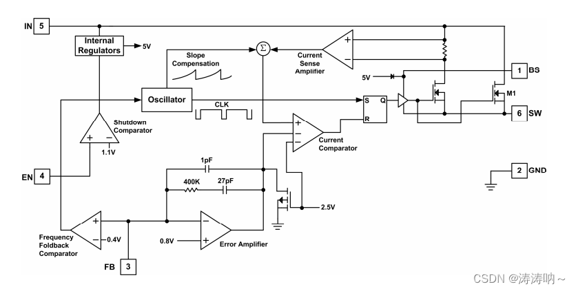
under these circumstances , It is equivalent to the moment when the switch is closed , Short circuit of power supply , The instantaneous current is very large , Make the chip burn out !
To verify that the chip has burned out , I welded a new one MP2359, There is no wrong diode connection in this circuit , At this time, the circuit successfully outputs 5V.
problem 3: It's solved 5V Problems caused by power supply voltage , that 3.3V Why can't the power supply voltage be generated smoothly ?
At this time, the senior suggested that my peripheral circuit might be short circuited , The voltage stabilizing module cannot output correctly .
So use a multimeter to test 3.3V Whether the peripheral output circuit is short circuited , The final measurement result is that the peripheral circuit is short circuited .
First, I will test the components without welding PCB Whether the board exists 3.3V Short circuit condition , The test found no such situation , Therefore, the components are short circuited or broken .
All components of my development board have been welded ,3.3V Supply power to multiple modules , It is troublesome to look for peripheral short circuit devices !
So I'm in the new PCB Re weld components on the board , Finally, it is confirmed that it is the problem of single-chip microcomputer welding , After re welding the components , The power module test is OK !
边栏推荐
- Basic concept and advanced level of behavior tree
- Phpcms applet plug-in version 4.0 was officially launched
- 0 basic how to make a cool leadership cockpit?
- Application of hidden list menu and window transformation in selenium
- 《一周搞定数电》——组合逻辑电路
- Self taught machine learning series - 1 basic framework of machine learning
- Pycharm [debug] process stuck
- [300+ continuous sharing of selected interview questions from large manufacturers] column on interview questions of big data operation and maintenance (I)
- 《一周搞定模电》—55定时器
- Behavior tree XML file hot load
猜你喜欢

Phpcms V9 background article list adds one click push to Baidu function

简析ROS计算图级

《一周搞定数电》-逻辑门

实践是成为网工最快的方法,网络工程师实战项目整理

Upgrade phpcms applet plug-in API interface to 4.3 (add batch acquisition interface, search interface, etc.)

Fix the problem that the rich text component of the applet does not support the properties of video cover, autoplay, controls, etc

ThreadLocal

《一周搞定模电》—55定时器

Yolov5 advanced III training environment

MySQL cannot be found in the service (not uninstalled)
随机推荐
Detectron2 save (according to maxap50) model during training_ best. PTH weight
Phpcms applet plug-in tutorial website officially launched
Yolov5 advanced camera real-time acquisition and recognition
Bbox format conversion (detectron2 function library)
Self taught neural network series - 3. First knowledge of neural network
Behavior tree XML file hot load
行为树XML文件 热加载
浅谈一下Type-C接口发展历程
教程1:Hello Behaviac
Pycharm [debug] process stuck
Analysis of ROS calculation diagram level
Statistics of various target quantities of annotations (XML annotation format)
phpcms v9商城模块(修复自带支付宝接口bug)
How to set the shelves and windows, and what to pay attention to in the optimization process
行为树的基本概念及进阶
Self taught neural network series - 1 Basic programming knowledge
[qnx hypervisor 2.2 user manual]12.2 terminology (II)
《一周搞定模电》—基本放大电路
Differences between commonjs and ES6 modularity
Some commands for remote work