当前位置:网站首页>Fplan power planning
Fplan power planning
2022-06-27 03:34:00 【Luca cat】
List of articles
Power supply is very important , There are many things to learn in this respect .
First of all, understand a little , The winding resources of a project are used in two parts , The winding resources of power supply and data signal . If the power takes up too much winding resources , Then the data signal will not have sufficient winding resources , There will be a lot of short problem . If the data signal takes up too much winding resources , Then the power supply may not be enough , This will affect the overall performance of the chip . Therefore, the winding resources of power supply and data should be reasonably allocated . Generally, the upper floor will be completely used for power supply , Because the thickness of high-rise metal is large and the resistance is small , Most suitable for power supply . Generally, the power supply is relatively dense at the beginning , In the later stage, if the winding resources are sufficient , That's natural , If the winding resources are insufficient , Some power cords can be deleted properly , Give the data signal .
The goal of power planning :
- 1. To all Macro Power supply
- 2. To all stdcell Power supply
- 3. To produce one that satisfies IR drop and EM( Electromigration ) Power supply network
- 4. Achieve DRC clear
1. Global power connection relationship
The global power supply is global net connect, It refers to connecting the corresponding ports and networks to the appropriate power and grounding networks
2.Followpins
Followpins Chinese Name: power rail , It's usually called power rail.Followpins Mainly to form standard cell Power supply network , And combine it with the chip core The power network inside is connected , For example, the power loop power ring And power cord power stripe.
3. Power cord
The crisscross power lines inside the chip are called power strips , Its purpose is to transmit the power supply to each part of the chip macro On .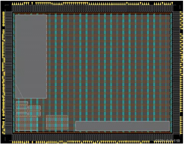
3.1 Basic setting method of the power strip

- Wv: This parameter is the width of the power strip in the vertical direction
- Wh: This parameter is the width of the power strip in the horizontal direction
- S1: This parameter is the minimum horizontal spacing of power strips of the same type
- S2: This parameter is the minimum vertical spacing of power strips of the same type
Wv and Wh Set up , A few rules of thumb :
When chip utilization is high , When the wiring congestion is high , Usually choose a fine power grid . If the chip utilization is very low , Then the wider the power grid is designed , The smaller the resistance on the wire , The smaller the voltage drop . Due to the small parasitic resistance of the high-level metal , Using high-level metal wiring can effectively reduce the voltage drop .
Wv: Longitudinal power width spacing pitch Integer multiple , The purpose is to make full use of the wiring channel . Its value cannot be too large , In general Do not exceed the minimum NAND gate width in the standard cell library 4 times . Each layer of metal pitch There are corresponding definitions in the physical library .
hypothesis M3 Of pitch yes 0.66, We get that the width of the smallest NAND gate in the outbound is 1.98, Its 4 Times 7.92, So if you use M3 Lay the power cord , Then W Value 0.66~7.92 Between 0.66 Integer multiple .
Wh:Wh Because the routing direction is horizontal , Therefore, its width value should be Integral multiple of standard cell height , Usually choose 1 Times or 2 times , At the same time, it should be smaller than that of the layer of metal in LEF Maximum defined width in file . When the horizontal congestion is not large, the 2 Times the height , If there is congestion, take 1 Times the height . Of course, many engineers like to set the power strip width to an integer , That's ok .
about power stripe Width and spacing design . Usually affected by different processes , There will be a big difference , It is a project that requires a lot of Power The task of design experience .
4. Power loop
For uniform power supply , The ring-shaped power supply metal ring surrounding the standard unit , It is also connected to the power supply I/O And standard units , Standard unit Power Rail and Power Stripe Also connected to the power ring .
Power ring How to calculate the width and spacing of :
Width :
Calculate the power consumption P( Various tools );
Set the width to W, High for H, The power consumption is P, be
Ptop = Pbottom = P * W / (W+H) * 0.5;
Pleft = Pright = P * H / (W+H) * 0.5;
The width of each side can be calculated as :
W(um) = I / J;
J Is the current density ,I(mA)=Pside/V, The current density can be found in the process library provided by the manufacturer .
The metal width should be 50% Margin of .
interval :
The spacing shall be determined according to the minimum spacing in the design rules provided by the manufacturer , Generally, it is the minimum spacing 2 About times .
边栏推荐
- A^2=E | 方程的解 | 这个方程究竟能告诉我们什么
- Il manque beaucoup de fichiers et de répertoires tels que scripts pendant et après l'installation d'anaconda3
- PAT甲级 1024 Palindromic Number
- 2020:MUTANT: A Training Paradigm for Out-of-Distribution Generalizationin Visual Question Answering
- [Shangshui Shuo series] day 6
- 超级详细,2 万字详解,吃透 ES!
- 2022中式面点师(高级)复训题库及在线模拟考试
- Nacos调用微服务两个问题:1.Load balancer does not contain an instance for the service 2.Connection refused
- Questions and answers of chlor alkali electrolysis process in 2022
- 2021:Check it again:Progressive Visual Question Answering via Visual Entailment通过视觉暗示进行渐进式视觉问答
猜你喜欢

使用promise的基本功能【四、Promise源码】

Il manque beaucoup de fichiers et de répertoires tels que scripts pendant et après l'installation d'anaconda3
fplan-电源规划

【promise一】promise的介绍与手撸的关键问题

文旅灯光秀打破时空限制,展现景区夜游魅力

Career outlook, money outlook and happiness outlook

Ledrui ldr6035 usb-c interface device supports rechargeable OTG data transmission scheme.

2021:Graphhopper: Multi-Hop Scene Graph Reasoning for Visual Question Answering

Calculation of average wind direction and speed (unit vector method)

Pat class a 1024 palindromic number
随机推荐
Resnet152 pepper pest image recognition 1.0
Ldr6028 OTG data transmission scheme for mobile devices while charging
Paddlepaddle 21 is implemented based on dropout with 4 lines of code droplock
一文教你Kali信息收集
再探Handler(上)(Handler核心原理最全解析)
[micro service sentinel] degradation rules slow call proportion abnormal proportion abnormal constant
2021:Passage Retrieval for Outside-KnowledgeVisual Question Answering通道检索的外部知识视觉问答
人间清醒:底层逻辑和顶层认知
I found a JSON visualization tool artifact. I love it!
我是怎样简化开源系统中的接口的开发的?
CVPR2021:Separating Skills and Concepts for Novel Visual Question Answering将技巧与概念分开的新视觉问答
Pat class a 1024 palindromic number
Anaconda3安裝過程及安裝後缺失大量文件,沒有scripts等目錄
PAT甲级 1024 Palindromic Number
733. image rendering
How to solve the problem of low applet utilization
Human soberness: bottom logic and top cognition
元透实盘周记20220627
PAT甲级 1023 Have Fun with Numbers
PAT甲级 1019 General Palindromic Number