当前位置:网站首页>Stm32cubemx learning (5) input capture experiment
Stm32cubemx learning (5) input capture experiment
2022-06-25 08:08:00 【Xiaohui_ Super】
Personal learning record
List of articles
One 、 New project

Two 、 Choose chip model
The development board I use is a punctual atom STM32F103ZET6 Core board

3、 ... and 、 Configure clock
The development board is welded with an external crystal oscillator , So I RCC(Reset and Cock Control) Configuration selected Crystal/Ceramic Resonator( Quartz / Ceramic resonator ), When the configuration is complete , Dexter Pinout view The relevant pins in the are marked green .

After the external high-speed clock configuration is completed , Get into Clock Configuration Options , According to the actual situation , Configure the system clock to 72 MHz, The configuration steps are as follows , Finally press enter , The software will automatically adjust the frequency division and frequency doubling parameters .

Four 、 Configure debug mode
ST-Link Namely Serial Wire Debug mode , Be sure to set !!!
I used to use M0 Chip , There is no problem if this mode is not configured , But now this model , If you don't configure Serial Wire Pattern , Once the program is passed ST-Link Burn into the chip , Chips can no longer be ST-Link Identified .( Later I passed STMISP Tool burning program / After erasing, it will return to normal )

5、 ... and 、 Timer ( Input capture ) Parameter configuration
I will TIM2 The passage of 1 Capture the test channel as input ,STM32CubeMX The default configuration will be PA0 Captured as input IO mouth (PA0 It has the multiplexing function , And no re image is required , So automatically PA0 Set to TIM_CH1 Of GPIO), The parameter setting of the timer is shown in the figure below ( The configuration of input capture may not be changed , Default capture rising edge ):

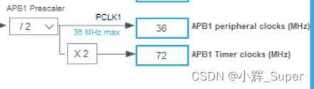
The frequency division coefficient is 72-1, It means 72 frequency division (0 Express 1 frequency division ,1 Express 2 frequency division , And so on ),TIM2 The clock frequency of is 72 MHz( The following figure ,APB1 Timer clocks The clock frequency of is 72MHz,TIM2 Mounted on APB1 On ). Make it 72 After frequency division , Frequency becomes 1MHz, Count per second 1000000 Time . The cycle is set to 1000-1( One less here , Should be Because the minimum count value is 0), Represents a complete timing period of 1000 Times count , Combined with timer counting frequency , The time required for a timer to overflow is 1ms.【 The frequency determines the capture period of the input capture , The timing value is set to 1000 Just for the convenience of calculation 】
Input to capture the interrupt that needs to start the timer , Interrupts are required for both timing overflow and input capture .

6、 ... and 、 Generate Keil engineering
Set up IDE and Project catalogue and name :

Store the code of each peripheral in a different .c /.h In file , Easy to manage ( Otherwise, they will be put in main.c in ).

Here is the generation Keil The project is about TIM2( Input capture ) Initialized code :
/* TIM2 init function */
void MX_TIM2_Init(void)
{


  /* USER CODE BEGIN TIM2_Init 0 */

  /* USER CODE END TIM2_Init 0 */

  TIM_ClockConfigTypeDef sClockSourceConfig = {
    0};
  TIM_MasterConfigTypeDef sMasterConfig = {
    0};
  TIM_IC_InitTypeDef sConfigIC = {
    0};

  /* USER CODE BEGIN TIM2_Init 1 */

  /* USER CODE END TIM2_Init 1 */
  htim2.Instance = TIM2;
  htim2.Init.Prescaler = 72 - 1;
  htim2.Init.CounterMode = TIM_COUNTERMODE_UP;
  htim2.Init.Period = 1000 - 1;
  htim2.Init.ClockDivision = TIM_CLOCKDIVISION_DIV1;
  htim2.Init.AutoReloadPreload = TIM_AUTORELOAD_PRELOAD_DISABLE;
  if (HAL_TIM_Base_Init(&htim2) != HAL_OK)
  {

    Error_Handler();
  }
  sClockSourceConfig.ClockSource = TIM_CLOCKSOURCE_INTERNAL;
  if (HAL_TIM_ConfigClockSource(&htim2, &sClockSourceConfig) != HAL_OK)
  {

    Error_Handler();
  }
  if (HAL_TIM_IC_Init(&htim2) != HAL_OK)
  {

    Error_Handler();
  }
  sMasterConfig.MasterOutputTrigger = TIM_TRGO_RESET;
  sMasterConfig.MasterSlaveMode = TIM_MASTERSLAVEMODE_DISABLE;
  if (HAL_TIMEx_MasterConfigSynchronization(&htim2, &sMasterConfig) != HAL_OK)
  {

    Error_Handler();
  }
  sConfigIC.ICPolarity = TIM_INPUTCHANNELPOLARITY_RISING;
  sConfigIC.ICSelection = TIM_ICSELECTION_DIRECTTI;
  sConfigIC.ICPrescaler = TIM_ICPSC_DIV1;
  sConfigIC.ICFilter = 0;
  if (HAL_TIM_IC_ConfigChannel(&htim2, &sConfigIC, TIM_CHANNEL_1) != HAL_OK)
  {

    Error_Handler();
  }
  /* USER CODE BEGIN TIM2_Init 2 */

  /* USER CODE END TIM2_Init 2 */

}
7、 ... and 、 Where is the interrupt function written
When using the standard library , We write interrupt handling in the bottom interrupt handling function , Such as EXTI0_IRQHandler(), but Hal The library adds a callback function , Will interrupt some necessary operations at the bottom “ hide ” Get up ( Such as clearing the interrupt ).
The order in which interrupts are called is ( With EXTI0 For example ):EXTI0_IRQHandler() —> HAL_GPIO_EXTI_IRQHandler() —> HAL_GPIO_EXTI_Callback().
TIM2 The interrupt service function of is already in stm32f1xx_it.c In the definition of (STM32CubeMX Automatically generated )
/** * @brief This function handles TIM2 global interrupt. */
void TIM2_IRQHandler(void)
{

  /* USER CODE BEGIN TIM2_IRQn 0 */

  /* USER CODE END TIM2_IRQn 0 */
  HAL_TIM_IRQHandler(&htim2);
  /* USER CODE BEGIN TIM2_IRQn 1 */

  /* USER CODE END TIM2_IRQn 1 */
}
HAL_TIM_IRQHandler() yes HAL The timer of the library is always interrupted , There's a lot of code inside , It's not shown here , All we need to know is —— When TIM2 Count value overflows or other events occur ( Such as capture of rising / Falling edge signal ) when , The system will execute a series of interrupt callback functions , This includes what we will use Count overflow callback function HAL_TIM_PeriodElapsedCallback() and Input capture callback function HAL_TIM_IC_CaptureCallback().
8、 ... and 、 Test examples
The serial port is used in the experiment , Not mentioned in the above configuration , For serial port configuration, please refer to STM32CubeMx Study (2)USART Serial port experiment
The core of my experimental code is the interrupt callback function :
//  Timer count overflow interrupt processing callback function
void HAL_TIM_PeriodElapsedCallback(TIM_HandleTypeDef *htim)
{

	if(IC_DONE_FLAG == 0)  //  Incomplete capture
	{

		if(IC_START_FLAG == 1)  //  High level has been captured
		{

			IC_TIMES++;  //  Capture times plus one
		}
	}
}

// Timer input capture interrupt processing callback function
void HAL_TIM_IC_CaptureCallback(TIM_HandleTypeDef *htim)//  Execute when capture interrupt occurs
{

	if(IC_DONE_FLAG == 0)  //  Incomplete capture
	{

		if(IC_START_FLAG == 1)  //  It turned out to be high level , Now capture a falling edge
		{

			IC_VALUE = HAL_TIM_ReadCapturedValue(htim, TIM_CHANNEL_1);  //  Get capture value
			TIM_RESET_CAPTUREPOLARITY(htim,TIM_CHANNEL_1);  //  First clear the original settings
			TIM_SET_CAPTUREPOLARITY(htim,TIM_CHANNEL_1,TIM_ICPOLARITY_RISING);//  Configured for rising edge capture
			IC_START_FLAG = 0;  //  Flag reset
			IC_DONE_FLAG = 1;  //  Complete a high level acquisition
		}
		else  //  Capture has not yet started , Capture the rising edge for the first time
		{

			IC_TIMES = 0;  //  The capture times are cleared
			IC_VALUE = 0;  //  The capture value is cleared
			IC_START_FLAG = 1;  //  Set the flag that captures the top edge
			TIM_RESET_CAPTUREPOLARITY(htim,TIM_CHANNEL_1);  //  First clear the original settings
			TIM_SET_CAPTUREPOLARITY(htim,TIM_CHANNEL_1,TIM_ICPOLARITY_FALLING);//  Configured for falling edge capture
		}
		__HAL_TIM_SET_COUNTER(htim,0);  //  The timer count value is cleared
	}
}
complete main.c
/* USER CODE BEGIN Header */
/** ****************************************************************************** * @file : main.c * @brief : Main program body ****************************************************************************** * @attention * * Copyright (c) 2022 STMicroelectronics. * All rights reserved. * * This software is licensed under terms that can be found in the LICENSE file * in the root directory of this software component. * If no LICENSE file comes with this software, it is provided AS-IS. * ****************************************************************************** */
/* USER CODE END Header */
/* Includes ------------------------------------------------------------------*/
#include "main.h"
#include "tim.h"
#include "usart.h"
#include "gpio.h"
#include <stdio.h>

/* Private includes ----------------------------------------------------------*/
/* USER CODE BEGIN Includes */

/* USER CODE END Includes */

/* Private typedef -----------------------------------------------------------*/
/* USER CODE BEGIN PTD */

/* USER CODE END PTD */

/* Private define ------------------------------------------------------------*/
/* USER CODE BEGIN PD */
/* USER CODE END PD */

/* Private macro -------------------------------------------------------------*/
/* USER CODE BEGIN PM */

/* USER CODE END PM */

/* Private variables ---------------------------------------------------------*/

/* USER CODE BEGIN PV */


uint32_t IC_TIMES;  //  Capture times , Company 1ms
uint8_t IC_START_FLAG;  //  Capture start flag ,1: High level captured ;0: High level has not been captured yet
uint8_t IC_DONE_FLAG;  //  Capture completion flag ,1: A high level acquisition has been completed
uint16_t IC_VALUE;  //  Enter the capture value of the capture

/* USER CODE END PV */

/* Private function prototypes -----------------------------------------------*/
void SystemClock_Config(void);
/* USER CODE BEGIN PFP */

/* USER CODE END PFP */

/* Private user code ---------------------------------------------------------*/
/* USER CODE BEGIN 0 */

/* USER CODE END 0 */

/** * @brief The application entry point. * @retval int */
int main(void)
{

  /* USER CODE BEGIN 1 */

	uint32_t time = 0;
  /* USER CODE END 1 */

  /* MCU Configuration--------------------------------------------------------*/

  /* Reset of all peripherals, Initializes the Flash interface and the Systick. */
  HAL_Init();

  /* USER CODE BEGIN Init */

  /* USER CODE END Init */

  /* Configure the system clock */
  SystemClock_Config();

  /* USER CODE BEGIN SysInit */

  /* USER CODE END SysInit */

  /* Initialize all configured peripherals */
  MX_GPIO_Init();
  MX_TIM2_Init();
  MX_USART1_UART_Init();
  /* USER CODE BEGIN 2 */

  HAL_TIM_IC_Start_IT(&htim2,TIM_CHANNEL_1);  // Turn on TIM2 Capture channel for 1
  __HAL_TIM_ENABLE_IT(&htim2,TIM_IT_UPDATE);  // Enable update interrupt

  /* USER CODE END 2 */

  /* Infinite loop */
  /* USER CODE BEGIN WHILE */
  while (1)
  {

		HAL_Delay(10);

		if(IC_DONE_FLAG == 1)  //  If a high level acquisition is completed
		{

			IC_DONE_FLAG = 0;  //  Sign clear
			time = IC_TIMES * 1000;  //  The pulse time is the number of acquisition  * 1000us
			time += IC_VALUE;  //  Plus capture time ( Less than 1ms Part of )
			printf("High level: %d us\n", time);
		}

    /* USER CODE END WHILE */

    /* USER CODE BEGIN 3 */
  }
  /* USER CODE END 3 */
}

/** * @brief System Clock Configuration * @retval None */
void SystemClock_Config(void)
{

  RCC_OscInitTypeDef RCC_OscInitStruct = {
    0};
  RCC_ClkInitTypeDef RCC_ClkInitStruct = {
    0};

  /** Initializes the RCC Oscillators according to the specified parameters * in the RCC_OscInitTypeDef structure. */
  RCC_OscInitStruct.OscillatorType = RCC_OSCILLATORTYPE_HSE;
  RCC_OscInitStruct.HSEState = RCC_HSE_ON;
  RCC_OscInitStruct.HSEPredivValue = RCC_HSE_PREDIV_DIV1;
  RCC_OscInitStruct.HSIState = RCC_HSI_ON;
  RCC_OscInitStruct.PLL.PLLState = RCC_PLL_ON;
  RCC_OscInitStruct.PLL.PLLSource = RCC_PLLSOURCE_HSE;
  RCC_OscInitStruct.PLL.PLLMUL = RCC_PLL_MUL9;
  if (HAL_RCC_OscConfig(&RCC_OscInitStruct) != HAL_OK)
  {

    Error_Handler();
  }
  /** Initializes the CPU, AHB and APB buses clocks */
  RCC_ClkInitStruct.ClockType = RCC_CLOCKTYPE_HCLK|RCC_CLOCKTYPE_SYSCLK
                              |RCC_CLOCKTYPE_PCLK1|RCC_CLOCKTYPE_PCLK2;
  RCC_ClkInitStruct.SYSCLKSource = RCC_SYSCLKSOURCE_PLLCLK;
  RCC_ClkInitStruct.AHBCLKDivider = RCC_SYSCLK_DIV1;
  RCC_ClkInitStruct.APB1CLKDivider = RCC_HCLK_DIV2;
  RCC_ClkInitStruct.APB2CLKDivider = RCC_HCLK_DIV1;

  if (HAL_RCC_ClockConfig(&RCC_ClkInitStruct, FLASH_LATENCY_2) != HAL_OK)
  {

    Error_Handler();
  }
}

/* USER CODE BEGIN 4 */


//  Timer count overflow interrupt processing callback function
void HAL_TIM_PeriodElapsedCallback(TIM_HandleTypeDef *htim)
{

	if(IC_DONE_FLAG == 0)  //  Incomplete capture
	{

		if(IC_START_FLAG == 1)  //  High level has been captured
		{

			IC_TIMES++;  //  Capture times plus one
		}
	}
}

// Timer input capture interrupt processing callback function
void HAL_TIM_IC_CaptureCallback(TIM_HandleTypeDef *htim)//  Execute when capture interrupt occurs
{

	if(IC_DONE_FLAG == 0)  //  Incomplete capture
	{

		if(IC_START_FLAG == 1)  //  It turned out to be high level , Now capture a falling edge
		{

			IC_VALUE = HAL_TIM_ReadCapturedValue(htim, TIM_CHANNEL_1);  //  Get capture value
			TIM_RESET_CAPTUREPOLARITY(htim,TIM_CHANNEL_1);  //  First clear the original settings
			TIM_SET_CAPTUREPOLARITY(htim,TIM_CHANNEL_1,TIM_ICPOLARITY_RISING);//  Configured for rising edge capture
			IC_START_FLAG = 0;  //  Flag reset
			IC_DONE_FLAG = 1;  //  Complete a high level acquisition
		}
		else  //  Capture has not yet started , Capture the rising edge for the first time
		{

			IC_TIMES = 0;  //  The capture times are cleared
			IC_VALUE = 0;  //  The capture value is cleared
			IC_START_FLAG = 1;  //  Set the flag that captures the top edge
			TIM_RESET_CAPTUREPOLARITY(htim,TIM_CHANNEL_1);  //  First clear the original settings
			TIM_SET_CAPTUREPOLARITY(htim,TIM_CHANNEL_1,TIM_ICPOLARITY_FALLING);//  Configured for falling edge capture
		}
		__HAL_TIM_SET_COUNTER(htim,0);  //  The timer count value is cleared
	}
}
/* USER CODE END 4 */

/** * @brief This function is executed in case of error occurrence. * @retval None */
void Error_Handler(void)
{

  /* USER CODE BEGIN Error_Handler_Debug */
  /* User can add his own implementation to report the HAL error return state */
  __disable_irq();
  while (1)
  {

  }
  /* USER CODE END Error_Handler_Debug */
}

#ifdef USE_FULL_ASSERT
/** * @brief Reports the name of the source file and the source line number * where the assert_param error has occurred. * @param file: pointer to the source file name * @param line: assert_param error line source number * @retval None */
void assert_failed(uint8_t *file, uint32_t line)
{

  /* USER CODE BEGIN 6 */
  /* User can add his own implementation to report the file name and line number, ex: printf("Wrong parameters value: file %s on line %d\r\n", file, line) */
  /* USER CODE END 6 */
}
#endif /* USE_FULL_ASSERT */
Experimental results :
PA0 It corresponds to a key on my development board , When touched ( Not pressed ) When this key is pressed , The serial port will keep printing some useless high-level duration , The duration of these useless pulses is very close to , All are 10ms about , It indicates that the duration of the jitter level of the key is about 10ms.
When you press and hold the key , Let go again , It will print the time when the key is pressed , For example, the data in the two red circles in the following figure , The first high level duration is 4.35s, The duration of the second high level is 1.59s.

边栏推荐
- ffmpeg+SDL2实现音频播放
- WebSocket的理解以及应用场景
- Force deduction 76 questions, minimum covering string
- TCP stuff
- 电子学:第008课——实验 6:非常简单的开关
- Sword finger offer (simple level)
- Solving some interesting problems with recurrence of function
- Dietary intervention reduces cancer treatment-related symptoms and toxicity
- DNS协议及其DNS完整的查询过程
- 自制坡道,可是真的很香
猜你喜欢

Electronics: Lesson 012 - Experiment 13: barbecue LED
Sword finger offer (simple level)

DNS协议及其DNS完整的查询过程

Neural network and deep learning-3-simple example of machine learning pytorch

Opencv daily function structure analysis and shape descriptor (8) Fitline function fitting line

取消word文档中某些页面的页眉
剑指offer刷题(简单等级)
FM信号、调制信号和载波

Network model -- OSI model and tcp/ip model

力扣 272. 最接近的二叉搜索树值 II 递归
随机推荐
电子学:第014课——实验 15:防入侵报警器(第一部分)
Apache CouchDB Code Execution Vulnerability (cve-2022-24706) batch POC
DNS协议及其DNS完整的查询过程
TCP stuff
初体验完全托管型图数据库 Amazon Neptune
【莫比乌斯反演】
Electronics: Lesson 010 - Experiment 8: relay oscillator
深度学习系列48:DeepFaker
Neural network and deep learning-3-simple example of machine learning pytorch
Authority design of SaaS system based on RBAC
Talk about the future of cloud native database
将数据导入到MATLAB
Electronics: Lesson 012 - Experiment 11: light and sound
[supplementary question] 2021 Niuke summer multi school training camp 9-N
数论模板啊
企业全面云化的时代——云数据库的未来
Niuke: flight route (layered map + shortest path)
Atlas conflict Remote Code Execution Vulnerability (cve-2022-26134 vulnerability analysis and protection
唐老师讲运算放大器(第七讲)——运放的应用
Deep learning series 45: overview of image restoration