当前位置:网站首页>Layer 2 and layer 3 forwarding principle based on VLAN
Layer 2 and layer 3 forwarding principle based on VLAN
2022-06-24 22:34:00 【Zhuge iron and steel cloud】
be based on VLAN Layer 2 / 3 forwarding principle based on
VLAN It is a protocol proposed to solve the broadcasting problem and security of Ethernet , It adds... To the Ethernet frame VLAN head , use VLAN ID Divide users into smaller workgroups , Restrict users' two-tier mutual visits between different working groups , Each workgroup is a virtual lan . The advantage of virtual LAN is that it can limit the broadcast range , And can form a virtual working group , Dynamically manage the network .
MAC Address
MAC(Media Access Control, Media access control ) The address is the hardware identification of the network device , Have uniqueness .MAC Address is also called physical address or hardware address , Burn in when produced by network equipment manufacturers NIC( Network interface controller ) in .MAC Long address 48 The bit , Break into pieces ID And equipment ID Two parts , front 24 Is it OUI(Organizationally unique identifier, Institution unique identifier ), after 24 Bits are allocated by the manufacturer .MAC The address is expressed in dotted hexadecimal , Pictured 1 Shown .

MAC Address format
MAC Addresses are usually divided into :
unicast MAC Address : unicast MAC The address uniquely identifies a terminal on the Ethernet , The address is fixed in the hardware ( Such as network card ) Inside .
Multicast MAC Address : The last bit of the first byte is 1( Usually, the 0x01 start ) Of MAC Address , Mark a group of equipment .
radio broadcast MAC Address :48 Bitwise holography 1 Of MAC Address , Mark all equipment in this network segment .
In the network, messages are transmitted in large byte order ( That is, the high byte is transmitted first ), The lower bits are transmitted first in bytes . therefore , If the first bit sent is 0 It's unicast , Otherwise, it is multicast or broadcast .
MAC Addresses can also be divided into :
dynamic MAC Address : The switch learns through data frames in the network , There is aging time ,MAC The corresponding relationship between address and port will change with the port of the switch to which the device is connected . The switching mechanism will disappear after power restart , Need to relearn .
static state MAC Address : Generated by configuration , It's not going to age ,MAC The correspondence between address and port is always the same , But the switch will also disappear after power restart , Need to reconfigure .
permanent MAC Address : Generated by configuration , It's not going to age ,MAC The correspondence between address and port is always the same , And the switching mechanism will not disappear after power restart .
Conflict domain and broadcast domain
Conflict domain ( The physical layer ): A network area where frames sent by different hosts or devices at the same time may conflict with each other . A collection of all workstations on a wire , Or a collection of all nodes on a physical network segment , Or the collection of nodes competing for the same bandwidth on Ethernet is a conflict domain . When conflict occurs , The transmitted frame may be damaged or disturbed , The conflicting host will be based on 802.3 Ethernet CSMA/CD The rule stops sending subsequent frames for a random period of time . The disadvantage is that the available bandwidth of each host is very low , When the number of host devices in the conflict domain increases , Cyber conflicts will multiply , The security of information transmission cannot be guaranteed . The devices connected by the hub are a typical conflict domain , Pictured 2 Shown .

Typical HUB The conflict domain
Broadcast area ( Data link layer ): A collection of all devices in the network that can receive broadcast frames sent by any device . All nodes that need to receive other broadcasts are divided into the same broadcast domain or logical network segment . Connected to the HUB It forms a broadcast domain with all nodes on the traditional switch port . When the switch receives a broadcast frame , It forwards the frame to every port except the port receiving the frame , Each connected device receives and processes the frame .
With the expansion of the network , The number of broadcast message encounters in the broadcast domain also increases . All these broadcast messages will seriously affect the network performance , If not managed properly , The whole network will crash .
A hub 、 Switch 、 Router
* A hub
Ethernet hub (HUB) After receiving Ethernet data frame from any port , Will broadcast the frame to all other ports . The hub corresponds to the physical layer , When the devices connected to different ports transmit data at the same time, it will cause conflicts , Therefore, the conflict domain and broadcast domain are all ports , Neither conflict domain nor broadcast domain can be isolated . Non commutative HUB Physical network segments cannot be divided , Because it doesn't divide the conflict domain .
* Bridges and switches
Bridges and switches are located at the data link layer , be based on MAC Address for data forwarding . Each physical port of the bridge and switch belongs to a conflict domain , All ports are in one broadcast domain . Both can isolate the conflict domain , But you can't isolate the broadcast domain , Cannot block broadcasts and logically segment the network .
Bridge and switch have the following differences :
The bridge has only a few ports ; The switch can have hundreds of ports .
Bridges are slower than switches , The switch adopts hardware ASIC The chip performs line speed forwarding and switching , Faster than the bridge .
The bridge adopts the mechanism of store and forward , Forward after receiving all data ; In addition to the storage mechanism, the switch also has a direct forwarding mechanism , Only after the frame header reaches the processing, it can be forwarded , You don't have to wait until all the data arrives , Therefore, the processing speed of the switch is faster than that of the bridge .
In view of the limitations of the bridge , Modern exchange LAN Bridges are rarely used in .
* Router
The router is located at the network layer , Conflict domain and broadcast domain can be isolated . Every subnet (subnet) Belongs to a broadcast domain , Broadcast cannot be sent between different subnets . therefore , To control the broadcast, you must use a router ( Or a three-layer switch with routing function ). After using the router , You can the network interface on the router (LAN Interface) Split the broadcast domain for units .
Generally, routers and switches are used to LAN Segmented into a large number of smaller conflict domains and broadcast domains . Traditional switch pair LAN The method of segmentation is shown in the figure 3 Shown .

Tradition LAN Segmentation
Although the switch can reduce the size of the conflict domain ( Each port is a conflict domain ), But hosts connected to all ports of the switch are still in a broadcast domain . The forwarding process of broadcast frames in a broadcast domain connected by traditional switches is shown in figure 4 Shown .

Broadcast on traditional switch
In the picture is an example by 5 Two layer two switches (SW1~5) Connected to a network composed of a large number of client hosts . Hypothetical host PC1 To work with the host PC2 signal communication . In Ethernet communication, the target must be specified in the data frame MAC The address can communicate normally , so PC1 It has to be broadcast first ARP Request information , To try to get PC2 Of MAC Address . Switch SW1 received ARP After broadcast frame , Forward it to all ports except the incoming frame port , therefore SW2 and SW3 Received the broadcast frame , They also forward frames to all their ports …… Finally, all hosts connected to the switch in the same network (PC2-PC8) All received the ARP request . so , Should have been sent to PC2 Of ARP Requests spread across the network , Not only consumes the overall network bandwidth , Moreover, the host that receives the broadcast frame also consumes a part CPU Time to deal with it . When the network is large , A large number of broadcast frames will seriously affect the network performance , Cause broadcast storm problem . Besides , Because the whole network is in a broadcast domain , All users can directly access and influence all parts of the network without control , And then threaten network security .
By default , The router does not forward broadcast traffic , Therefore, it can be used to divide the broadcast domain . Creating a broadcast domain with a router will reduce broadcast traffic , And provide more bandwidth for unicast communication , Each router port is connected to a separate network , The broadcast traffic is limited to the LAN In segment . But usually there are few router network interfaces (1~4 about ), The number of broadcast domains that can be divided is limited , And the cost of router is higher than that of switch . Layer 2 switches generally have multiple network interfaces , If it can be used to divide the broadcast domain , Will greatly improve the freedom of network design .
VLAN
VLAN(Vitual Local Area Network, Virtual LAN ) It is a technology that divides the physical network into multiple logical LANs . One VLAN It's a broadcast domain , That is, a logical subnet , Sites within it can be located in different physical locations LAN On , But the sites communicate freely as if they were on the same common LAN without the restriction of physical location . utilize VLAN technology , The network manager can according to the actual application needs , The user logic in the same physical LAN is divided into different broadcast domains on the layer-2 switch , Make users with the same requirements or services in the same broadcast domain , Users with different needs or services are in different broadcast domains .
No... Is set Vlan On the layer 2 switch of , Any broadcast frame is forwarded to all ports except the receiving port . To configure Vlan after , When the switch belongs to Vlan After a port of receives a broadcast frame , To ensure that they belong to the same Vlan All hosts of receive the broadcast frame , The switch must forward according to the following principles :
1) Send to the same... In this switch Vlan Other ports in ;
2) The message sent to this switch contains this message Vlan All convergence links of , So that the same... Can be found on other switches Vlan The port of also sends the frame .
chart 5 Give two... Created on the switch Vlan after , An example of a broadcast frame sent by a host being forwarded . For illustration purposes , In red 、 Blue and blue are different Vlan( In actual use, it is indicated by Vlan ID To distinguish between ). Which port 1、2 It's red Vlan, port 3、4 It's blue Vlan.

Vlan Split the broadcast domain
so , from PC1 The transmitted broadcast frame is only forwarded to the same Vlan Other ports in the , Both belong to red Vlan The port of 2, It will not be forwarded to blue Vlan The port of . That's it ,Vlan The broadcast domain is divided by limiting the range of broadcast frame forwarding , To improve network efficiency and security .
Vlan It can be understood as logically dividing a switch into several virtual switches , And these virtual switches are not connected to each other .Vlan It's the broadcast area , Usually, the two broadcast domains are connected by a router , Data frames between broadcast domains are relayed by routers . therefore ,Vlan Routers are also required for communication between ( Or layer 3 switch ) Providing relay services , namely “Vlan Routing between ”. stay Vlan Configure routers between , send Vlan Internal flow still passes through the original Vlan Internal two-layer network , From a Vlan To another Vlan The traffic is forwarded in three layers through routing , After being forwarded to the destination network, the data frame is finally sent to the destination host through the layer-2 switching network . The router does not forward Ethernet broadcast frames , so Vlan The router configured between the does not change the partition Vlan The purpose of isolated broadcasting achieved .
VLAN The frame format
* Ethernet V2 MAC The frame format
Ethernet MAC There are two standard frame formats , namely DIX(DEC,Intel,Xerox) Ethernet V2 standard (RFC894) and IEEE 802.3 standard . chart 6 Shown is the commonly used Ethernet V2 Of MAC The frame format ( Factual standard ):

Ethernet V2 Of MAC The frame format
Ethernet frames are transmitted at the link layer , So source and purpose MAC Address is also called link layer address (link layer address), Also known as L2 Address 、 Layer 2 address or hardware address .
type (Type) The field indicates what protocol is used by the upper layer . Common protocol type values are shown in table 1 Shown :
surface 1 Common protocol type values
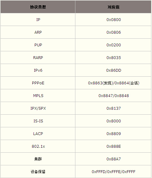
data (Data) The field is the data content carried by the frame , A protocol data unit consisting of an upper layer protocol PDU constitute . The data length is 46~1500 Between , If the upper layer protocol data unit length is less than 46 byte , Then the rest of the field must be populated , In order to make sure MAC The frame length shall not be less than 64 byte .
so , The range of Ethernet frame length is 64~1518 byte .
Be careful : Contracting tools such as Testcenter Setting the length of the contract will CRC Take into account , That is, the frame length contains CRC Of 4 byte ; And packet capturing tools such as Wireshark The displayed frame length does not include CRC Field .
* belt VLAN Ethernet frame format
IEEE 802.1Q( Be commonly called Dot One Q) Standard in Ethernet data frame “ Send source MAC Address ” And “ Category fields (Type Field)” Add... Between 4 Bytes of Vlan Identifying information ( label ), Pictured 7 Shown :

Insert Vlan Ethernet frame format after
TPID(Tag Protocol Identifier, Label protocol ID ) The value is specified as 0x8100. By default, the device adopts the... Specified in the protocol TPID value , Switch through TPID To determine whether a data frame is attached based on IEEE802.1Q Of VLAN Information .
TCI(Tag Control Information, Label control information ) Fields are divided into Pri、CFI and VLAN In the third part of .Pri Indicates message priority ( Also known as 1p priority 、COS or 1q priority ),CFI(Canonical Format Indicator) identification MAC Whether the address is encapsulated in a standard format in different transmission media , Usually it is 0( A standard format ).Vlan ID Identify the... To which the message belongs VLAN Number , The value range is 0~4095, commonly 0 and 4095 Retain ( ZTE equipment Vid=0 Express priority-tagged frame ).
In a switched network environment , Ethernet frames come in two formats : Some frames do not have a four byte label attached , It is called unlabeled frame (ungtagged frame), Some frames are tagged with four bytes , It is called tagged frame (tagged frame).
Based on port partition Vlan in , Every 802.1Q Each port is assigned a default Vlan ID, be called PVID(Port Vlan ID) Or port default Vlan ID(default Vid),CISCO be called native Vlan. All received by the port untagged Frames are considered to belong to the port default Vlan ID, And default on the port Vlan ID Forward inside .
Be careful , To insert or strip Vlan The data frame will be recalculated when labeling CRC.
VLAN Links and ports
* VLAN Link type
Vlan The links within can be divided into :
Access link (Access Link, Or access link ): There will be no or unrecognizable Vlan Tagged equipment ( Such as user host ) Connect to configuration Vlan Switch port . It can only be transmitted without labels (untagged) Ethernet frame , And only with one Vlan relation .
Convergence link (Trunk Link, Or arterial link 、 Relay link ) : Connect two that can identify Vlan Tagged equipment ( Such as switch ), Can be transmitted to multiple Vlan With labels (tagged) frame , Can work with multiple Vlan Related to .
Hybrid link (Hybrid Link): It can transmit frames without labels , The frame of the belt label can also be transmitted . But for a particular Vlan, All frames transmitted must be of the same type , For a Vlan, The transmitted frame is either unlabeled , Or carry the same label .
Displays the differences between the three links :

Vlan Link type
When planning an enterprise network , It is very likely to encounter the situation that users belonging to the same department are scattered on different floors of the same building , At this point, you may need to consider how to set up across multiple switches Vlan. In the network shown in the figure below , Set the four hosts on different floors to the same through the convergence link Vlan.

Convergence link
As shown in the figure ,PC1 The data frame sent is from SW1 Arrive through the convergence link SW2 when , In the frame, a red symbol is attached Vlan The label of .SW2 After receiving data frame , Check Vlan The tag finds that the frame is red Vlan, Therefore, after the label is removed, it can be removed as required ( unicast 、 Broadcast or multicast ) The recovered data frame is forwarded to other data frames that are red Vlan The port of .
If convergence link is not used , A red switch shall be set on each of the two switches 、 blue Vlan Special interface and interconnection with network cable ( Access link ). But the vertical wiring between the building floors is troublesome , Generally, it can't be carried out by the grass-roots managers at will . and ,VLAN The more , Between floors ( Strictly speaking, between switches ) The more ports you need to interconnect , Low port utilization , It also limits the expansion of the network .
The convergence link carries multiple Vlan The data of , Heavy load , Therefore, the convergence link must support 100Mbps Above the transmission speed .
By default , The convergence link forwards all the data on the switch Vlan The data of , That is, the convergence link belongs to all the nodes on the switch Vlan. In practical applications, it may not be necessary to forward all Vlan data , Therefore, in order to reduce the switch load and bandwidth waste , The user can set limits on the number of devices that can be interconnected via the convergence link Vlan.
VLAN Port type
According to Vlan Frame recognition , The type of switch port ( Pattern ) It is divided into Access port 、Trunk Port and Hybrid port .
Access port : The port connecting the user host on the switch , Only access links can be connected .Access The port belongs to only one Vlan, And only to the Vlan Forwarding data frames . The Vlan Of Vid = port PVid, so Vlan All ports in the are in untagged state .Access The port receives frames from the host , Add... To the frame Tag label ; When sending frames to the host , The... In the frame Tag Peel off the label .
Trunk port : A port on a switch that connects to other switches or routers , Only converging links can be connected .Trunk Ports allow multiple Vlan The tagged frame of passes , Keep... When sending and receiving frames Tag label . In what it belongs to Vlan in , about Vid = port PVid Of Vlan, It is in Untagged port state ; about Vid ≠ port PVid Of Vlan, It is in Tagged port state .
Hybrid port : The switch can be connected to the port of user host and other switches , It can be connected to both the access link and the aggregation link .Hybrid Ports allow multiple Vlan Through the frame of , In addition, some Vlan The frame of Tag Peel off the label .
Be careful ,Access、Trunk and Hybrid Port is the appellation of a certain port by the manufacturer , Is not IEEE802.1Q Protocol standard definitions .
Access The port belongs to only one Vlan,PVid That's where it is Vlan, Therefore, there is no need to set ;Trunk and Hybrid The port belongs to more than one port Vlan, So we need to set PVid( Default is 1). If the port is set PVid, When the port receives a message without Vlan Tag The data frame of , Add... To the frame Tag Mark (Vid Set as the default to which the port belongs Vlan Number ) And forward it to PVid The port of ; When the port sends Vlan Tag The data frame of , If you receive a frame Vlan Tag And port PVid identical , Stripping Vlan Tag Then send the frame .
Hybrid Port and port Trunk The port handles data in the same way , The difference is that when sending data :Hybrid Ports allow multiple Vlan Data frames of are sent without labels , and Trunk Only the default port is allowed Vlan Data frames of are sent without labels . On the same switch Hybrid Port and Trunk Ports cannot coexist , Available in actual use Hybrid Instead of Trunk.
Ben Hybrid Port of PVid And the connected peer switch Hybrid Port of PVid It has to be consistent .
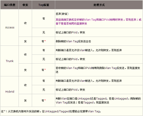
Due to different port types , The switch processes frames differently . The following table describes different port types .
surface 2 Different port types Vlan Frame processing mode
VLAN Port status
Switch ports can be configured to belong to one or more Vlan. Port status means that it is in a Vlan The state of , This status determines that the port receives tagged or untagged The processing method of the frame . For each Vlan, Ports have two states , namely Tagged port and Untagged port. The same port can be different Vlan ID Set up Tagged or Untagged.
When configuring the port to which it belongs Vlan when , If so Vlan Of Vid = port PVid when , Then the port is here Vlan In the Untagged port state ; if Vid ≠ port PVid, Then the port is here Vlan In the Tagged port state .
PVid It is only related to the entry direction of the message , For the unlabeled frame entering the switch, the entry port will be marked PVid label ; Each data frame in the switch is labeled .Tagged/Untagged It is only related to the exit direction of the frame , The outgoing port is Untagged port Of , When forwarding a frame, the label in the frame should be stripped , Otherwise keep the label .
VLAN The divisions
The access link can be set in advance , be called “ static state Vlan”; It can also be dynamically set according to the connected host , be called “ dynamic Vlan”.
* static state VLAN
static state Vlan Also known as port based Vlan (Port Based Vlan), That is, specify which port belongs to Vlan, As shown in the figure below .

Based on port partition Vlan
Divide according to ports Vlan It is most commonly used because of its simplicity . But because you need to specify port by port Vlan, Therefore, when there are many hosts in the network , The operation becomes very complicated . also , Each time the host changes the connected port , The port must also be changed Vlan Set up —— This is obviously not suitable for networks that need to change their topology frequently .
* dynamic VLAN
dynamic Vlan There are mainly :
be based on MAC Address of the Vlan (MAC Based Vlan)
Based on subnet Vlan (Subnet Based Vlan)
User based Vlan(User Based Vlan)
……
The difference is mainly based on OSI Refer to the information of which layer of the model to determine the port Vlan. Determine which port belongs to Vlan The information used in OSI The higher the level in , The more adaptable it is to build a flexible network .
Network equipment manufacturers may use private protocols to implement subnet based and user based Vlan, Therefore, compatibility problems may occur when equipment from different manufacturers are interconnected .
* be based on MAC Address of the VLAN
be based on MAC Address of the Vlan, It is through querying and recording the host network card connected to the port MAC Address to determine the port Vlan. Assume MAC-A The address is set by the switch to belong to Vlan10, No matter MAC-A The host of the address is connected to which port of the switch , This port will be divided into Vlan10 Inside , As shown in the figure below .

be based on MAC Address partition Vlan
be based on MAC Address partition Vlan, All connected hosts must be investigated during initial setup MAC Address and record , A lot of work . And this division method will reduce the execution efficiency of the switch , Because each port of the switch may have many Vlan A member of the group , In this way, broadcast packets cannot be restricted . Besides , If the host ( Like a laptop ) Change the network card frequently , Have to change frequently Vlan Set up .
* Based on subnet VLAN
Based on subnet Vlan, Through the connected host IP Address to determine the port Vlan. All data frames of the same subnet belong to the same Vlan, Thus, users in the same subnet are divided into one Vlan Inside ( Similar to routers ). Even if the host MAC Address change , As long as it IP The address remains the same , You can still add the original settings Vlan, As shown in the figure below .

Based on subnet partition Vlan
be based on IP Subnet partition Vlan The network segment can be divided according to the transmission protocol , It is conducive to organizing users for specific application services . also , Users can move freely within the network without reconfiguring the host , Especially in use TCP/IP Users of .
The disadvantage of this method is efficiency , Because checking the network layer address of each packet is time-consuming . At the same time, there may be more than one port Vlan Members of , It can not effectively suppress broadcast messages .
* User based VLAN
User based Vlan, Is based on the currently logged in user on the host connected to each port of the switch , To determine which port the port belongs to Vlan. The user identification information is generally the login user of the host operating system , Such as Windows The user name used in the domain .
* Protocol based VLAN
Protocol based Vlan Divide the physical network into protocol based logic Vlan. When the port receives a frame , its Vlan Determined by the protocol type in the frame . for example ,IP、IPX and Appletalk There may be separate Vlan,IP Broadcast frames are only sent to IP Vlan All ports in .
* Multicast address based VLAN
Multicast address based Vlan Dynamically created by multicast packets . For example, each multicast packet corresponds to a different one Vlan, Ensure that multicast data frames are only received by the ports connected to the corresponding multicast packet members . This method of division is inefficient , Not suitable for LAN . But because it will Vlan Expand to wide area network , Therefore, it is more flexible , And it is easy to expand through the router .
* Based on strategy VLAN
Based on strategy Vlan yes Vlan The most basic definition of . Every input ( No label ) Frames are viewed in the policy database , The database determines which... The frame belongs to Vlan. For example, establish a special e-mail system between the company's management personnel Vlan Strategy , So as not to be seen elsewhere .
This division is the most flexible , With automatic configuration capability , It can connect relevant users , It is called in logical division “ Networks ”. The network administrator only needs to determine the partition in the network management software Vlan The rules of ( Or attributes ), When the site joins the network, it will be “ perception ”, And is automatically included in the correct Vlan in . meanwhile , It can also automatically identify and track the movement and changes of the site .
be based on VLAN Forwarding and routing
Vlan The hosts of internal communication belong to the same broadcast domain , The traffic between hosts is forwarded directly through the layer-2 network ;Vlan The hosts for inter communication are located in different broadcast domains , The host cannot pass directly ARP Broadcast the request to the other party's address , At this time, the communication must be completed with the help of a three-layer router .
The router can be regarded as each Vlan Gateway for , Therefore, the host that communicates with each other through the router must know the existence of the router and its location Vlan Interface address on ( The default gateway ). After configuring the default gateway on the host , For span Vlan Communication for , The host will automatically find the default gateway , And send the message to the default gateway for forwarding instead of directly sending it to the destination host .
so , When the purpose of the message MAC The address is the gateway address ( Router or layer 3 switch MAC Address ) when , This message is a three-layer message .
* Layer 2 Forwarding
be based on Vlan The layer-2 forwarding process mainly includes : Identify and find Vlan、 Find and learn sources MAC、 Search for purpose MAC And forward the data frame .
1) Identify and find Vlan: When the switch port receives a data frame , First, through TPID Value to determine whether the frame is labeled [1].
if tagged frame , And Vid≠0, The port belongs to Vlan Find the... In the frame label in the table Vid Whether there is , If exist , Then go to the next step , Otherwise, the frame is discarded ( Or submit CPU Handle );
if tagged frame , And Vid=0( namely priority frame [2]), Then add a port to the frame PVid Make it tagged frame ;
if untagged frame , Then add a port to the frame PVid And assign priority to make it tagged frame .
notes :① To improve processing efficiency , All data frames inside the switch carry Vlan label , Deal with... In a unified way . Therefore, it is necessary to check the label of the data frame input to the switch and label it as needed .
②802.1Q Vlan In the environment , Frames can be divided into tagged、untagged and priority-tagged Three .Tagged The frame is based on the label it carries Vid Conduct MAC Learn to forward .Untagged and Priority-tagged After the frame enters the switch port, it will be processed according to PVid Conduct MAC Learn to forward .
2) Find and learn sources MAC: The switch is in MAC Forwarding table (Mac+Vid+Port) Find the receiving frame in Vid The corresponding source MAC Table item , If not found, learn the frame receiving source MAC ( take “ Source MAC+Vid+Port” Add to MAC In the table ); If found, update the aging time of the table item .
notes :MAC Address learning only learns unicast addresses , Do not learn broadcast and multicast addresses . Multicast MAC The entry is passed by CPU Configuration creation .
3) Search for purpose MAC: If the purpose MAC Broadcast or multicast , Then in the Vlan Broadcast or multicast ; Otherwise, in the MAC Look in the table to see if Vid The corresponding purpose MAC Table item .
4) Forwarding data frames : If in MAC An exact match was found in the table DMAC+Vid Table item , Then the frame is forwarded to the corresponding port in the table entry ( If the corresponding port is a frame receiving port , Then the frame should be discarded ); Otherwise, report to the Vlan All ports except the receiving port flood the frame ( Flooding broadcasts unknown unicast frames instead of broadcast frames ).
The figure shows the general flow of layer 2 forwarding .

Layer 2 forwarding process
【 example 】 Data frames from PC1 Forward through one switch to a connected to another switch PC2 And get a response , As shown in the figure below .

PC1 towards PC2 Send a message
Suppose two switches have just been powered on ( here MAC The address table is empty ), The specific forwarding process is as follows :
①PC1 The sent data frame enters the switch SW1 Of Access After the port , By port PVid add Vid=100 The label of . The switch sends the frame to the source MAC Address deposit MAC Address table ( Study ), And flood the frame to Vid=100 All ports ( In addition to the input port );
②SW1 Of Trunk The port belongs to Vid=100 Of Vlan, So accept this mark as 100 Of Tagged Data frame ; And the port is in Vid=100 Up for Tagged port, Therefore, the data frame is sent out of the switch SW1 when , Don't change Tagged Frame structure ;
③Tagged The frame arrives at the switch SW2 Of Trunk port , because Trunk The port has VID=100 Of Vlan, So accept this frame ; The Trunk The port does not change Tagged Frame structure , It's a source of learning MAC After the address, flood the data frame to all Vid=100 The port of ( In addition to the input port );
④SW2 Of Access The port received the frame , Peel the of the frame Tag Label and send to PC2.
⑤PC2 received PC1 Data frame sent , And send a response frame to PC1.
⑥ After forwarding similar to the previous process , The response frame arrives at the switch SW1. The switch found the purpose of the frame MAC The address is already in MAC In the address table , Forward only to PC1.
so , Both sender and receiver belong to the same Vlan Communication for , All processing is completed in the layer-2 network .
Three layer routing
* Router routing
Use a router to Vlan When routing between , There are roughly two kinds of :
1) Use multiple router ports to connect with each router Vlan Connect .
2) The interface between a single router and the switch Trunk Port connection ( be called dot1Q Connect ), Make more than one Vlan Share the same physical connection to the router .
The way 1 Set each port on the switch for interconnection with the router as the access link , Then use the network cable to connect with the independent port on the router . As shown in the figure below , There are two on the switch Vlan, Two ports shall be reserved on the switch for interconnection with the router ; The router also needs to have two ports ; The two are connected by two network cables .

Every Vlan A physical connection
Pictured , Every Vlan Must monopolize a switch port and a router port , And a network cable needs to be laid again . And routers usually LAN The interface is limited , This undoubtedly brings scalability problems .
The way 2 Set the switch port used to connect the router as the aggregation port , And the convergence port on the router must also support . The protocol used by both parties for converging links must also be the same . Then define the corresponding on the router Vlan Of “ A subinterface (Sub Interface)”. Although there is only one physical port actually connected to the switch , But in theory, it can be divided into multiple virtual ports . As shown in the figure below .

Vlan Trunking
Use this Vlan Trunking technology , Can make multiple Vlan Business flows share the same physical connection , Each frame is distinguished by passing the tagged frame on the aggregation chain Vlan Of traffic . Usually ,Vlan The traffic between routes is insufficient to reach the line speed of the link , Use Vlan Trunking Configuration of , It can improve the bandwidth utilization of the link , Save port resources and simplify management ( New network Vlan You only need to set a new one on the router Vlan Sub interface of , No need to rewire )
【 example 】 Different Vlan The flow of data when communicating with each other , As shown in the figure below .

Different Vlan The communication process between the
host PC1 Through the communication target IP Address (192.168.2.1) Compared with subnet mask calculation, it is found that PC2 It does not belong to the same network segment as this computer , No direct access . according to IP Communication rules ,PC1 Look up the local routing table and find the corresponding gateway . In the real network , The host usually only configures the default gateway (Default Gateway,GW), so PC1 Find the default gateway . then ,PC1 In this machine ARP Find the default gateway in the cache ( The router ) Of MAC Address , If not, send an out broadcast ARP Request frame , Its purpose MAC The address is full 1, Source MAC The address is local MAC Address , Requested IP The address is gateway 192.168.1.100. From the router ARP Get the router in the unicast response frame MAC Address R after , Next, follow the steps shown in the figure to PC2 Sending data frames ①, Its purpose MAC The address is the router address R、 But the purpose is IP The address is still the ultimate object of communication PC2 The address of .
The switch is on the port 1 Data frame received on ① after , retrieval MAC Address table and port 1 Belong to the same Vlan Table items of . The aggregation link is considered to belong to all Vlan, So port 6 It also belongs to the retrieval object . After searching, the switch knows to MAC Address R When sending data frames , Need to go through port 6 forward .
From the convergence port 6 When sending data frames , Will attach Vlan Identifying information . Data frame in the figure ② Added the original red Vlan After label , Enter the convergence link . Router receives data frame ② after , Confirm that Vlan label , To be in charge of red Vlan The sub interface receives .
next , According to the routing table inside the router , Determine where to forward . Because of the target network 192.168.2.0/24 It's blue Vlan, And the network is directly connected with the router through the sub interface , So just take charge of blue Vlan Just forward the sub interface . At this time, the purpose of the data frame MAC The address was changed to PC2 Of MAC Address ; Because it needs to be forwarded through the aggregation link , So it belongs to blue Vlan Identification information ( Data frame ③).
Switch receives data frame ③ after , according to Vlan Label from MAC The search in the address table belongs to blue Vlan Table items of . Because of the communication target PC2 Connect on port 3 And the port is an access port , Therefore, the switch peels the data frame Vlan After label ( Data frame ④) Forward to port 3, Final PC2 Successfully received PC1 Sent data frame .
so ,Vlan When we communicate with each other , Even if both sides are connected to the same switch , It has to go through “ The sender → Switch → Router → Switch → The receiving party ” Such a process . During layer 3 routing forwarding , Data packets IP The address remains the same ,MAC The address will change at each node .
* Layer 3 switch routing
Use VLAN Trunking after , Use traditional router to Vlan There are some deficiencies in the performance of inter routing : Because the router adopts general purpose CPU, Forwarding depends entirely on software processing , At the same time, it supports various communication interfaces , Bring a great burden to the software . The software shall process, including message receiving 、 check 、 Find the route 、 Option handling 、 Message fragmentation, etc , The result is that the performance cannot be very high . Just Vlan In terms of inter route , Traffic will be concentrated on the converging link part of the interconnection between routers and switches , This part is easy to become a speed bottleneck .
because Vlan Communication between is relatively simple , Just check the routing table , Therefore, the switch can be integrated into a special chip for checking the routing table (ASIC), Realize the functional integration of layer 2 switching and layer 3 routing , Layer 3 switch (Layer 3 Switch).
The design of layer-3 switch is based on IP Careful analysis of routing , Extract IP A simplified process that each message must go through in routing :
IP Most messages in the route do not contain IP Options , Therefore, there is no need to process messages in most cases IP Options ;
Different network messages have different lengths , To support the interconnection of various heterogeneous networks ,IP The function of message fragmentation is realized , But in an all Ethernet environment , Data frame ( message ) Fixed length , Therefore, the message fragmentation function can be reduced ;
The layer 3 switch adopts different methods to match the longest address mask of the router , Use exact address matching to deal with , It is helpful for hardware to realize fast search ;
The layer 3 switch adopts Cache Method , Put the recently used host routes into the hardware lookup table . Only in this Cache Items that cannot be matched in the are forwarded through the software . such , Only the first message of each stream is forwarded by software , Then a large amount of data flow can be completed in hardware , Greatly improve forwarding performance .
Refer to the following diagram for the internal structure of the three-layer switch .

Internal structure diagram of layer 3 switch
Pictured , The built-in routing module is the same as the switching module , Use ASIC Hardware handles routing . therefore , Compared with the traditional router , High speed routing can be realized . also , The routing and switching module is connected by an internal aggregation link , It can ensure considerable bandwidth .
Corresponding to IP In the network model , Every Vlan Corresponding to one IP Network segment , The layer-3 forwarding engine in the layer-3 switch is in each network segment (Vlan) Forward message between , Realization Vlan Interworking between , Therefore, the routing function of layer 3 switch is usually called Vlan Routing between (Inter-VLAN Routing).
When connecting using a router , It's usually needed in LAN The interface is set to correspond to each Vlan Sub interface of ; Layer 3 switches are internally generated “VLAN Interface (VLAN Interface)”, For each Vlan Sending and receiving data . stay Cisco Of Catalyst Series switch ,VLAN The interface is called SVI(Switched Virtual Interface, Exchange virtual interfaces ). Every time a layer 3 switch is created Vlan It will automatically generate one SVI. stay SVI After the interface is set to the default gateway , And configure the host gateway to connect with the switch SVI identical , You can achieve different Vlan Routing between nodes .
Use a layer 3 switch to Vlan Inter router routing is similar to connecting routers and switches using aggregation links , That is, you need to go through “ The sender → Switching module → Routing module → Switching module → The receiving party ” The process of .
【 example 】 Suppose the network is shown in the figure 19 After connecting , All equipment is in initial state , No message has been sent out . if PC1 It is known that PC2 Of IP Address , You can go through ping Command send ICMP Message to know PC1 Can we get to PC2. This process is analyzed below .

ping Process network topology
⑴ PC1 Put oneself IP And subnet mask 255.255.255.0 Phase and get the network number 1.1.1.0, take PC2 Of IP Match the subnet mask to get the network number 2.2.2.0, hear PC2 Not in the same network segment as yourself . therefore PC1 Retrieve the routing table to get the default gateway .PC1 To pass information to the gateway , But this time PC1 in ARP Table is empty , So to the default gateway ( Switch layer 3 interface ) issue ARP Request frame , Request gateway MAC Address . The purpose of the frame MAC The address is full 1, Source MAC The address is local MAC Address , Requested IP The address is gateway 1.1.1.1;
⑵ SW received ARP Request frame , Attach ports to it PVid(10) The label of ;
⑶ SW use ARP Of the request frame Mac1 and Vid10 lookup MAC Forwarding table , Found no such item , Then learn , That is, add... To the table “Mac1—Vid10—Port1” The record of ; And the source IP and MAC Correspondence of (“1.1.1.2—Mac1”) It was recorded that ARP surface , Indicate the purpose IP by 1.1.1.2 The purpose of data frame forwarding MAC by Mac1, At the same time, it needs to be routed to the port Port1;
⑷ ARP The destination address of the request is the broadcast address ,SW Flood it to the Vlan Each port of ( In addition to the port ); meanwhile SW I intercepted a copy and sent it to CPU( gateway ), Discovery is asking yourself MAC, So I replied ARP Unicast response frame , Purpose MAC by PC1 Of Mac1, Source MAC For the gateway MAC Address GwMac1, Source IP by 1.1.1.1, Purpose IP by PC1 Of 1.1.1.2;
⑸ PC1 received SW It's from ARP Answer frame , obtain SW Three layer gateway MAC Address , take “1.1.1.1—GwMac1” It was recorded that ARP surface .PC1 towards SW send out ICMP Request frame , Purpose IP by PC2 Of IP(2.2.2.2), Purpose MAC Gateway MAC, Source IP And the source MAC by PC1 Of ;
⑹ SW received ICMP Request frame , Attach ports to it PVid(10) The label of , Then the source MAC Address learning , It is found that the item is posted on the second floor , Update aging time . For the purpose of this frame MAC The address is gateway ,SW Send to layer 3 routing processing .
⑺ On the third floor, first check IP The version of the message 、IP First inspection and TTL Whether it is right , If it is not correct, the mark is discarded and handed over to CPU Handle ; If it is correct, it is in the layer 3 host routing table ( also called L3 surface ) Find the purpose in IP( namely PC2 Of IP 2.2.2.2). here L3 Only those directly connected to you are included in the table 32 Bit address ( Including its own interface ) And steps ⑶ in ARP The form is issued after learning PC1 Information , And can't find PC2 Information about . Then search the subnet routing table according to the longest prefix matching algorithm ( also called Longest Prefix Match namely LPM surface ) obtain 2.2.2.1 Entry of destination network segment , The next dance IP The address is 2.2.2.1;
⑻ Index back to L3 Look up 2.2.2.1, Get the entry , Found to submit CPU Handle (CPU It also needs to be regarded as a port );
⑼ CPU Not to PC2 The routing , but PC2 Purpose IP Own interface address 2.2.2.1 The network segment , Therefore, the interface Vlan20 All physical ports contained broadcast a ARP Request frame , Source MAC The address is layer 3 of the switch interface MAC Address GwMac2, Source IP The address is 2.2.2.1, request IP Address 2.2.2.2 Of MAC Address ;
⑽ PC2 received ARP request , Study “2.2.2.1—GwMac2” Join in ARP surface ; And the reply ARP Answer frame , Purpose IP Interface to the switch Vlan20 Of IP Address 2.2.2.1, Purpose MAC Interface to the switch Vlan20 Of MAC Address GwMac2;
⑾ SW received PC2 Sent ARP Answer frame , Additional ports PVid(20) In the after MAC Find in table “Mac2+Vid20”, If you don't find the learning source address , stay MAC Add... To the forwarding table PC2 Relevant records . For the purpose of this frame MAC Is the gateway address , Therefore, it is submitted to three-tier treatment ;
⑿ The third layer first checks the correctness of the message , If there is no mistake, it is in L3 Search purpose in the table IP. For the purpose of IP For this machine , So send it to CPU Handle .CPU After processing the message, we get “2.2.2.2—Mac2” Add relevant information to ARP surface (CPU Issue to L3 Record in table ).
⒀ PC1 towards SW The first one sent ICMP The request frame is stored in memory , It's up to CPU Conduct IP Message header modification (TTL reduce 1,FCS Recalculate encapsulation ) and MAC encapsulation ( Purpose MAC The address is changed to PC2 Of MAC Address , Source MAC The address is changed to SW Three layers MAC Address ) And send it to PC2, If it times out, discard ,CPU send out ICMP Timeout to PC1;
⒁ PC2 received PC1 It's from ICMP After the request , reply ICMP Answer frame , Purpose IP by PC1 Of IP 1.1.1.2, Again PC2 It is found that the address is not in the same subnet as yourself , The gateway is required to forward . Before PC2 Learned the switch interface Vlan20 Of ARP, At this time, according to the ARP take ICMP Answer frame purpose MAC Fill in the address as gateway MAC Address GwMac2 Send out . After the switch receives the frame , Purpose of discovery MAC The address is the gateway address , Take out the destination in the frame IP Address 1.1.1.1 Find the route . The switch has learned this before IP The routing , Therefore, the corresponding route in the host routing table will be found and the frame will be sent to the destination MAC Change the address to Mac1, Source MAC Change the address to gateway MAC Address GwMac2, Send to port Port1 On . Final ,PC1 Just received PC2 Of ICMP The reply .
⒂ After the above process ,PC1 and PC2 Learn the of their gateway interfaces respectively ARP, The switches have also arrived separately PC1 and PC2 The routing . Subsequent messages will no longer pass through the route , And directly by L3 The corresponding items in the table are forwarded by hardware .
Be careful , The steps in this example are compared with “ Router routing ” A little more detail , The added part is not the difference .
* VLAN Inter communication acceleration
Vlan When routing between , Not all data needs to pass through the built-in routing module of external router or layer 3 switch . for example , Use FTP(File Transfer Protocol, File transfer protocol ) When transferring large files with a capacity of more than a few megabytes , because MTU(Maximum Transfer Unit, Maximum transmission unit ) The limitation of ,IP The protocol will divide the data into small pieces, transmit them and reassemble them at the receiver . These segmented data have the same source / Purpose IP Address and (TCP/UDP) Port number . Such a stream of data is called “ flow (Flow)”. As long as the initial data of the stream is correctly routed , Subsequent data should be routed in the same way , In fact, there is no need for the router to handle .
Three layer switch for high-speed communication Vlan When routing between , The first piece of data of the whole stream is still forwarded by the switching module → Routing module → The switching module forwards to the port to which the target is connected . At this time , Record the first data routing result into the cache and save it . Information to be recorded / Purpose IP Address and (TCP/UDP) Port number 、 Switch transceiver port number and forwarding target MAC Address, etc .
After the second block and subsequent data of the same stream arrive at the switch , Directly find out the forwarding port number by querying the information previously saved in the cache, and then forward it to the port connected to the target . such , There is no need to relay through the internal routing module repeatedly , And the cache information inside the switch is enough to determine which port to forward . At this time , The switch handles the data frame similarly when it is relayed by the router , Such as rewriting MAC Address 、IP In Baotou TTL and Check Sum Check code information, etc .
if Vlan Inter route information changes , The routing module will send control information to the switching module , The switch reestablishes the forwarding path , Forward... As usual .
By caching routing results on the switch , At cable speed (Wired Speed) Receive the data transmitted by the sender 、 And can route at full speed 、 Forward to the receiver .
* Routers and switches work together to build LAN
Although layer-3 switches can provide higher speed routing processing than traditional routers , But there is still a need to use routers in the network . Its necessity is mainly reflected in the following aspects :
Used with WAN Connect . Most layer 3 switches are only equipped with LAN( Ethernet ) Interface . A few high-end switches are also used to connect WAN Serial interface or ATM Interface , But in most cases, the connection WAN You need a router .
Ensure network security . On the layer 3 switch , Through packet filtering can also ensure a certain degree of network security . But using the various network security functions provided by the router ( Packet filtering 、 be based on IPSec structure VPN、 utilize RADIUS User authentication, etc ), Users can build a more secure and reliable network .
Support TCP/IP Other than the network architecture . Even though TCP/IP It has become the mainstream network protocol architecture , But there is still a lot of Internet use Novell Netware Under the IPX/SPX or Macintosh Under the Appletalk Wait for the network protocol . In the layer 3 switch , Except for some high-end models, it basically only supports TCP/IP. Routers are essential for environments that require other network protocols .
notes : A few high-end switches can also support the functions of the above routers . for example Cisco Of Catalyst6500 Series can be selected with WAN Connected interface module ; There's also an alternative based on IPSec Realization VPN Module ; And can support TCP/IP Other network protocols besides .
The following figure shows a combination of router and switch LAN Example .

The combination of router and switch to build LAN
Use the layer 2 switch configured on each floor to define Vlan, Connect TCP/IP Client host . Between the floors Vlan Inter communication is realized by high-speed routing of three-layer switch . If the network environment requires high reliability , Redundant configuration of layer 3 switches can also be considered . And WAN The connection of , Then it is implemented through routers with various network interfaces , And through the packet filtering and filtering of the router VPN And other functions to achieve network security . Besides , Using router can also support Novell Netware etc. TCP/IP Outside the network .
By using Vlan Building a LAN , Users can divide the broadcast domain freely without the restriction of physical links . Provided by router and layer 3 switch Vlan Routing between , Able to adapt to flexible network structure . But because of the use of Vlan Easily lead to network complexity , Therefore, the composition of the whole network will be difficult to grasp . Especially because of the crisscross flow of data , In the event of a failure , Accurate positioning and troubleshooting can be difficult .
VLAN Expand
* VLAN Translation
Vlan Conversion is also called Vlan Translation or Vlan mapping , It allows different Ethernet switches for edge access Vlan ID The settings overlap each other , Via Ethernet switch Vlan Conversion function , Repeat different switches Vlan ID Change to a different Vlan ID, And send it from the uplink port , Thus, the user isolation is realized in the layer-2 core switch , To simplify the setup of edge access switches .
for example PON In the system , adopt Vlan Conversion mode ,OLT or ONU The device will send the uplink Ethernet frame to the user Vlan label (Vid It may not be used alone , Other users in the same system may use the same Vid) Switch to the only network side Vlan label ; And perform the opposite operation in the downward direction .
* QinQ
With the massive deployment of Ethernet technology in the operator network ( Metro Ethernet ), utilize IEEE 802.1Q Vlan The isolation and identification of users are greatly limited . because 802.1Q Defined Vlan The label field can only represent 4096 individual Vlan(12 The bit ), For a large number of users who need to be identified in man, they are short of money , therefore QinQ Technology came into being .
QinQ( Also known as Stacked Vlan namely Vlan Stack or Double Vlan) Technology comes from IEEE 802.1ad standard , Yes, based on IEEE 802.1Q The image name of the encapsulated tunneling protocol .QinQ Realize in the original 802.1Q Vlan label ( Inner label , Also known as Customer Vlan,CVlan) Add another Vlan label ( Outer label , Also known as Service Provider Vlan,SVlan), The outer public label blocks the private label of the inner user , Make the message carry two layers Vlan The label crosses the backbone network of the operator ( Public network ), When reaching the network edge switch at the other end of the user, the outer public network is stripped Vlan label , Restore the inner user tag to facilitate the next step of communication . so ,QinQ Technology can not only effectively expand Vlan Quantity space ( As many as 4096×4096 individual ), And it can provide a simple two-layer VPN( Virtual private network ) Tunnel , It is especially suitable for small enterprise network or small LAN with three-layer switch as the backbone .
* QinQ Message format
QinQ The message encapsulation format is shown in the figure below . Internal layer during public network transmission Vlan The label is the user's private network Vlan label , Outer layer Vlan Tags are assigned by the operator to the user . The private network Vlan Labels are transparently transmitted , So different users Vlan Labels can be reused , Just the outer layer Vlan The label is unique on the public network .

QinQ Message encapsulation format
Some manufacturers will QinQ Of the outer label of the message TPID Value is set to 0x9100 Or other values . For interworking with these devices , The user shall be able to configure TPID value , Send to the public network QinQ Frames carry TPID The value is the same as that of other manufacturers . because TPID The position of the field in the Ethernet frame is the same as that without Vlan In frame protocol type of tag (Type) The fields are in the same position , In order to avoid confusion of data frame forwarding and receiving in the network , Users are not allowed to TPID The value is configured as a common protocol type value .
* QinQ Encapsulation
QinQ Encapsulation is how to put a single layer Q The message is converted into two layers Q message , Encapsulation mainly occurs in the user oriented of man UPE equipment , It is generally carried out on the switched port . According to different packaging basis ,QinQ Can be divided into port based QinQ、 Flow based QinQ And routing sub interfaces QinQ encapsulation .
* Port based QinQ encapsulation
Port based encapsulation means that all traffic entering a port is encapsulated in an outer layer Vlan. When the port receives a message , Whether or not the message has Vlan label , The switch will attach the default port for this message Vlan The label of . If the received message has been tagged , Then the message becomes a double label message ; If the received message is not labeled (untagged), The message will carry the default of this port Vlan label . Port based QinQ Encapsulation is easy to implement , Therefore, the three-layer switches of mainstream manufacturers in the industry support . The disadvantage is that the outer layer Vlan The label encapsulation method is rigid , When multiple different users or user networks Vlan Users cannot be distinguished when accessing the same port , That is, you cannot select multiple outer labels on a port according to the service type , Thus, it is difficult to effectively support the flexible operation of single port and multi services .
Besides , Additional links are required based on port encapsulation , Complex networking , Not conducive to extended maintenance .
* Flow based QinQ encapsulation
Flow based QinQ Encapsulation first classifies the flow of data entering the port , Then, for different data streams, select whether to insert outer labels and which outer labels to insert , Therefore, it is also called flexible QinQ(Smart QinQ or Selective QinQ). When some data flows ( Such as multicast ) No outer label is added to the exit , Or a single port according to the inner layer Vlan When adding different outer labels , You need flexibility QinQ.
flexible QinQ According to the flow classification method, it can be subdivided as follows :
1) According to the Vlan Section diversion
When different businesses of the same user use different Vlan when , According to the Vlan Section for diversion , Such as PC surf the internet Vlan The scope is 101~200,IPTV Of Vlan The scope is 201~300,VoIP Of Vlan The scope is 301~400. After the user oriented device receives the user data , according to Vlan Range , Insert for Internet service 100 The outer label , Yes IPTV Insert 300 The outer label , Yes VoIP Insert 500 The outer label .
2) According to the Vid+Priority shunt
Different businesses have different priorities , When multiple services of the same user use the same Vlan when , It can be distinguished according to the priority of different businesses , Then insert different outer labels .
3) According to the purpose of the message IP Address diversion
Be the same PC It includes both Internet service and voice service , Different business purposes IP Different , available ACL For purpose IP Address for shunting , Then insert different outer labels .
4) according to ETYPE Conduct QinQ encapsulation
When the same user includes PPPOE The Internet service , It also includes IPOE Of IPTV When the business , These terminals all pass through a Vlan The upside , According to the PPPoE(0x8863/8864) and IPoE(0x0800) Messages are different ETYPE The agreement number acts as QinQ The basis of diversion .
Current flexibility QinQ It is mainly used for operators to access the network . In the operator's network, an Vlan, To facilitate problem tracking and prevent mutual visits between different users , Use outer labels to distinguish user applications ; Or use the outer label to distinguish different access locations in the access environment , Use the inner and outer labels to uniquely identify an access user .
* Routing sub interface QinQ encapsulation
QinQ Encapsulation is usually carried out directly on the switched port , But in special cases QinQ It can also be encapsulated on the routing sub interface .
When the core network adopts VLL/PWE3 When transparently transmitting user data ,NPE The routing sub interface on the device can be based on the user Vlan ID Package outer layer Vlan, Through the outer layer Vlan Access VLL/PWE3. Through a QinQ Stacking Sub interface to transparently transmit multiple user identifications Vlan ID.
This approach is also flow based QinQ encapsulation , but QinQ Stacking Sub interfaces can only be associated with L2VPN(PWE3/VLL/VPLS) It's the combination that makes sense , Layer 3 forwarding is not supported .
* QinQ Message forwarding
The port of the layer-3 switch connecting the user network is called Customer port , The port connecting the backbone network is called Uplink port , The edge access equipment of the backbone network is called PE(Provider Edge). Generally, the user side network passes through Trunk Access to the backbone edge switch , Within the backbone network Uplink Port by Trunk Symmetrical connection .
Through QinQ Implement simple layer 2 VPN In the process of , The message is forwarded as follows :

QinQ Message forwarding process
When the message is sent from the user side network 1 Reach the edge switch of the operator's backbone network Switch A Of Customer Port time , Whether the message carries a tag or not ,Switch A Are based on port PVid Force the outer label into it (Vid=10). Inside the backbone network , The message follows Vlan10 Of Trunk Port propagation , The user's private label remains transparent in the backbone network , Until you reach the edge switch Switch B.
Switch B Discovery and user networks 2 The connected port is Customer port , According to the tradition 802.1Q The protocol strips the outer label , Restore to the original message of the user , Forward to the user side network 2, So as to realize a simple two-layer VPN function .PE Outer layer for access point SVlan Isolation , Safe and economical Vlan. The management of users can be based on the outer layer SVlan And the inner layer CVlan Unique location .
Easy to know , if Vlan It maps to C→S+C, Then for Vlan The stack ; if Vlan It maps to C→S, Then for Vlan transformation .
Be careful ,MAC Address learning 、 Spanning trees, etc. are based on outer layers SVlan.
* QinQ Advantages and disadvantages
utilize QinQ When providing access services, it has the following advantages :
Ÿ It can solve the increasingly scarce public network Vlan The question of resources ;
Ÿ Users can plan their own private network Vlan ID, Not with the public network Vlan ID Conflict ;
Ÿ Provide a simple two-tier VPN Solution ;
Ÿ Make the user network more independent , When the service provider upgrades the network , The user network does not have to change the original configuration ;
Ÿ It can be divided into different levels Vlan ID Differentiate between different businesses , To provide different pipes differently 、QoS Strategy ;
ŸQinQ Technically, it can be nested at multiple levels , Only limited by Ethernet frame length , It has good expansibility .
But as the number of users increases ,QinQ The model also brings scalability problems . Some users may want to carry their own... When transferring data between branches Vlan ID, This makes use of QinQ Technology management service providers face the following two problems : For the first customer Vlan Identification may conflict with other customers ; Service providers will be severely limited by the number of logos that customers can use . If users are allowed to use their own Vlan ID Space , Then the core network still exists 4096 individual Vlan The limitation of .
* PVlan(Cisco)
PVLAN(Private VLAN, private VLAN) That is, all workstations are in the same subnet , But the workstation can only communicate with its own default gateway .PVlan Use two layers Vlan Isolation technology , Only the upper level Vlan The whole picture can be seen , The lower Vlan Isolate each other . If each port of the switch is divided into one ( The lower )Vlan, Then all ports are isolated .
Every Private Vlan There are two kinds of Vlan: Lord Vlan(Primary Vlan) And the auxiliary Vlan(Secondary Vlan), The latter is divided into isolation Vlan(Isolated Vlan) And groups Vlan(Community Vlan).
PVlan Communication range :
Lord Vlan Can be isolated from all associated with it Vlan、 group Vlan signal communication . Different master Vlan No ports between can communicate with each other ( here “ Communicate with each other ” Refers to two-layer connectivity ).
group Vlan Can be in the same group Vlan Community port communication within , It can also be used with PVlan Hybrid port communication in . Every PVlan There are multiple groups Vlan.
Isolation Vlan Do not be in the same isolation as Vlan Other isolated port communication in , Can only communicate with hybrid ports . Every PVlan There can only be one isolation in the Vlan.
Accordingly , There are three types of switch physical ports :
Isolation port (Isolated port), Connect to the user , It belongs to isolation Vlan. Can only communicate with hybrid ports , Can't communicate with each other .
Community port (Community port), Belong to a group Vlan. Not only can it communicate with hybrid ports , It can also communicate with other physical ports in the same community .
Hybrid port (Promiscuous port), Connect to router or layer-3 switch interface , Belong to the Lord Vlan. The traffic it receives can be sent to the isolation port and the community port .

PVlan Port type
Pictured ,port1、port2 and port3 The three are isolated from each other , Communication is not allowed , Only with port6 signal communication ;port4 and port5 Can communicate between , with port6 signal communication . All ports only need to share one IP Address .
PVlan It is very effective to ensure the data communication security of the access network . All users are connected to PVlan, One for each user Vlan, The two layers of users are isolated from each other . Users only need to connect to their own default gateway , One PVlan You don't need more than one Vlan and IP The subnet can provide a connection with layer-2 data communication security .PVlan The function can guarantee the same Vlan The ports in can't communicate with each other , But you can go through Trunk port . So even if the same Vlan Users in , And they're not affected by the broadcast .
For upper layer switches , It can be considered that there are only a few masters in the lower layer switch Vlan, And don't care about the Lord Vlan The port in actually belongs to Vlan, This simplifies configuration and saves Vlan resources . A master Vlan All of the Private Vlan In the same subnet , The number of subnets and IP Address resources .
PVlan Usually used for intranet , Used to block communication between network devices connected to certain interfaces or interface groups , But it allows communication with the default gateway . Although each device is in a different PVlan in , But the same IP subnet .
* SuperVlan
Different Vlan Inter communication needs to be forwarded through three-layer routing , And each subnet (Vlan) You need to set a routing address . For each subnet allocated , There are three IP Address ( The network number of the subnet 、 Broadcast address and default gateway ) occupied . meanwhile , This inherent constraint on address allocation also severely reduces the flexibility of addressing , Many idle addresses are wasted . In order to improve IP Address utilization ,Super VLAN Supernet came into being .
SuperVlan( also called VLAN Aggregation, namely Vlan polymerization ) Take more than one Vlan(SubVlan) Aggregate into one SuperVlan, these SubVlan Share a common use of IP Subnets and default gateways . adopt VLAN Aggregation enables all end users on the same subnet to pass through a unified route ( Same subnet segment address ) And use different broadcast domains .
utilize SuperVlan technology , Just for SuperVlan Assign a subnet address , And set up a for each user or subnet SubVlan. all SubVlan Flexible distribution SuperVlan In the subnet IP Address , Use SuperVlan The default gateway of . Every SubVlan It's a separate broadcast domain , Ensure isolation between different users ;SubVlan Inter communication needs to be through SuperVlan Routing . Because of the various SubVlan No real subnet segment is required , Can effectively improve IP utilization . Such a subnet can be allocated small enough and easy to expand , There is no need to redefine the subnet size .
SuperVlan Hosts in use the same network segment address , Share the same uplink gateway . Even if it belongs to different SubVlan The host , Because its address belongs to the same subnet , Devices will think that they are layer 2 interworking , Can do layer 2 forwarding , It will not be sent to the gateway for layer 3 forwarding . But in fact SubVlan They are isolated from each other on the second floor , So we need to use ARP agent (Proxy) To achieve SubVlan The intercommunication between .Subvlan Communication between and with the outside world through ARP agent , all Subvlan Sent by the internal host ARP All requests are made by SuperVlan Of MAC Address as ARP The reply .
Be careful ,SuperVlan Does not include physical ports , Think of it as a three-tier concept of logic —— A number of SubVlan Set . For switching chips SuperVlan It's transparent , Still press... In the chip Vlan Forward . In port based Vlan in , Layer 2 communication , Neither sending nor receiving will be targeted SuperVlan Message of . Enter SubVlan The data frame of the device will be attached to this SubVlan The label of , from Trunk When the port is issued, it will not be changed to SuperVlan The label of .
* ARP Proxy principle
A physical network subnet (Subnet) The source host in sends a message to the destination host in another physical network subnet ARP request request , The gateway directly connected to the source host uses its own interface MAC Address instead of destination host reply ARP reply The reply , The process is called ARP agent .
ARP The basic process of agency is as follows :
The source host sends a message to the destination host in the subnet of another physical network ARP request ;
The gateway connected to the source host network is enabled ARP Agent function , If there is a normal route to the destination host , Instead of the destination host answering its own interface MAC Address ;
Sent by the source host to the destination host IP The packets are sent to the router ;
The router does the normal work for the packets IP Routing and forwarding ;
To the destination host IP The message passes through the network , Finally reach the destination host .
* SubVlan Three layers of communication between
【 example 】SuperVlan 2 contain SubVlan 21 and SubVlan 22, analysis PC1 And PC2 Interworking process of ( hypothesis PC1 Of ARP None in the table PC2 Corresponding table item ).IP Address and MAC The address is shown in the figure below .

use ARP The proxy implementation is different SubVlan Three layers of communication between
PC1 To send a message to PC2, Will PC2 Of IP Address (1.1.1.3) And your own network segment 1.1.1.0 /24 Compare . because SubVlan 21 and SubVlan 22 Belong to the same SuperVlan The subnet you are in , So they broadcast ARP request PC2 Of MAC Address ; and PC2 It's not in SubVlan 21 In the broadcast domain , Unable to receive the ARP request . When PC1 On the second floor ARP When a request has no response in its broadcast domain , The switch gateway is running ARP agent , Look up the routing table and find that the next hop is the direct connection routing interface (SubVlan 22), Then send a... On this interface ARP request PC2 Of MAC Address ; obtain PC2 After response , Just put the gateway on its own MAC Address GwMac As PC2 Of MAC Address ( the truth is that Mac2 ) Give back PC1 ( Different devices implement slightly different ). after , host PC1 To be sent PC2 All messages are sent to the switch , The layer-3 switch performs normal layer-3 forwarding .
PC2 Send back to PC1 The message forwarding process and the above PC1 To PC2 The message flow of is similar .
* SuperVlan Communication with external three layers
【 example 】 Switch 1 On the configuration SuperVlan 2、SubVlan 21 and 22, And have a normal Vlan 10. Switch 2 Configure two normal Vlan 10 and 20. hypothesis SuperVlan 2 Next SubVlan 21 Medium PC1 Want to access the switch 2 Next PC3, Analyze the forwarding process of uplink and downlink messages .

Super VLAN Three layer communication with the outside
* Message uplink process
PC1 (1.1.1.2/24) To visit PC3(1.1.3.2/24), because IP The address is not in a network segment , so PC1 send out ARP Request to your own gateway , Request gateway's MAC Address .SubVlan21 received ARP After the message , Send it to CPU.CPU lookup SubVlan and SuperVlan Correspondence of , Know how to respond SuperVlan2 Of MAC Address ( Different device implementations may vary slightly ), And know that the response message should be from SubVlan21 Send to PC1.
PC1 Learn about gateways MAC After the address , Start sending destination MAC by SuperVlan2、 Purpose IP by 1.1.3.2 Message of .SubVlan21 After receiving the message , Purpose of test MAC After that, we know that three-layer forwarding should be carried out , So we look up the forwarding routing table , It is found that the next hop address is 1.1.2.2, The output interface is Vlan10, And pass ARP Table entries and MAC The table entry identifies the port , Send the message to the switch 2, Switch 2 Send the message to according to the normal forwarding process PC3.
* Message downlink flow
PC3 Response message , At the switch 2 Go to the switch according to the normal forwarding process 1, Now the switch 1 Find the forwarding route table entry , The discovery destination address is PC1(1.1.1.2), The corresponding output interface is SuperVlan2. but SuperVlan2 Does not contain any ports , So how to determine the outgoing port of the message ?
A closer look reveals , Although the forwarding routing table 1.1.1.2/24 The outgoing interface of the network segment is SuperVlan2, But in ARP In the table IP Address 1.1.1.2 The corresponding output interface is SubVlan 21. The output interface used by the chip when it is really used to build the republication should be ARP Corresponding to SubVlan Interface , By means of SubVlan Next, find the purpose MAC Address to find the correct outbound port . therefore ,PC3 The response message can arrive normally PC1.
Be careful , If located in a SuperVlan Computers in the run high-level applications based on broadcast or multicast , These applications are limited to SubVlan Inside . therefore , High level applications should be carefully analyzed , It can only be used when there is no multicast or broadcast based application SuperVlan.
VLAN Three layer interworking of VLAN Communication principle
https://blog.51cto.com/wn2100/2130076
https://www.cnblogs.com/xieyunc/p/9784041.html
【 The editors recommend 】
边栏推荐
- Docker 安装 Redis-5.0.12,详细步骤
- How does flutter use the online transcoding tool to convert JSON to model
- Kubevela v1.2 release: the graphical operation console velaux you want is finally here
- Genesis public chain and a group of encryption investors in the United States gathered in consensus 2022
- AQS源码分析
- In the era of full programming, should I give up this road?
- Fanuc robot_ Introduction to Karel programming (1)
- Heartless sword Chinese English bilingual poem 003 The sea of books
- NIO、BIO、AIO
- Heavyweight! Fada is listed as a "specialized and new" enterprise
猜你喜欢

干货丨产品的可行性分析要从哪几个方面入手?

零代码即可将数据可视化应用到企业管理中
![[personal experiment report]](/img/04/c9e1bee19bff9d55b73c531f7b17f4.png)
[personal experiment report]

Creating files, recursively creating directories

nuScenes——数据集配置过程中遇到图像文件缺失或大小为0时的补救方法

Chapter 10 project communication management

SAP interface debug setting external breakpoints

The logic of "Ali health" has long changed

Ideal L9, new trend of intelligent cockpit
理想L9,智能座舱新潮流
随机推荐
Huada 4a0gpio settings
为什么有的程序员能力一般却能拿到好offer?
socket(2)
直播软件app开发,左右自动滑动的轮播图广告
Interrupt, interrupted, isinterrupted differences
OA system -- save the verification code to session
字符串习题总结2
Power system | IEEE paper submission process
一个女孩子居然做了十年硬件。。。
Genesis公链与美国一众加密投资者齐聚Consensus 2022
EasyBypass
证件照处理
2022-06-16 工作记录--JS-判断字符串型数字有几位 + 判断数值型数字有几位 + 限制文本长度(最多展示n个字,超出...)
DX 的 HLSL 和 GL 的 GLSL的 矩阵构建的行列区别
AQS source code analysis
AQS源码分析
Main steps of system test
【个人实验报告】
软件设计的七大原则
Short video mall system, how does scroll view adapt to the remaining height of the page