当前位置:网站首页>Arm architecture and programming 7 -- exceptions and interrupts (based on Baiwen arm architecture and programming tutorial video)
Arm architecture and programming 7 -- exceptions and interrupts (based on Baiwen arm architecture and programming tutorial video)
2022-07-24 01:28:00 【Mountains】
One 、ARM For exceptions ( interrupt ) Process of use :
1、 initialization
1) Set interrupt source , Allow it to generate interrupts .
2) Set interrupt controller ( shielding 、 Priority, etc ).
3) Set up CPU Main switch , To interrupt .
2、 Execute user program
3、 The interrupt
Interrupt signal –> Interrupt controller –>CPU
4 、 Check
CPU Every time an instruction is executed , Check for interruptions 、 Abnormal generation .
5、 Handle
Found something unusual 、 Interrupt generation , Start to deal with .
For different exceptions , Will jump to different addresses to execute the program .
Two 、 The processing flow of interrupts by processors of different architectures
2.1 Cortex-M3、M4 series
2.1.1 Interrupt processing flow
Cortex-M3、M4 After the interruption ,
1、 Save the scene 、 Hardware complete
2、 Resolution interrupt 、 Hardware complete
3、 Jump to vector table , Hardware complete
4、 Restore the scene , Software triggers 、 Hardware recovery
Hardware does most of the work , The software only needs to provide an interrupt function .
2.1.2 Abnormal vector table
Here is Cortex-M3、M4 Interrupt vector table of , The exception vector table contains the specific function address of an interrupt , When the interrupt occurs, it will execute the code at the corresponding address .

2.2 Cortex-A7 series
2.2.1 Interrupt processing flow
Cortex-A7 After the interruption ,
1、 Switch mode : Hardware
2、 Jump to perform : Hardware
3、 Save the scene : Software
4、 Identify interrupt sources 、 Handle : Software
5、 Restore the scene : Software
The hardware is only responsible for switching mode and jumping to an interrupt instruction execution .
2.2.2 Abnormal vector table
Cortex-M3、M4 For each exception, there is a corresponding interrupt function , but Cortex-A7 No ,Cortex-A7 There are jump instructions . He puts several interrupts in the same mode together , Become a big category , Then use software to distinguish interrupts . Put an interrupt entry for a certain type of exception .

Some knowledge about interruption , Prior to F103 It is introduced in the study notes , I won't explain it here .
3、 ... and 、 Save the scene
Although the interrupt processing flow of different architectures is different , But the main steps are the same , There are three steps .
1、 Save the scene
2、 Resolution anomaly , Call the corresponding exception handling function
3、 Restore the scene
For unused processors , The specific processing work is different :
Save the scene :cortex M3/M4 It's done in hardware ,cortex A7 Such as software implementation
Resolution anomaly / interrupt :cortex M3/M4 It's done in hardware ,cortex A7 Such as software implementation
Call handler :cortex M3/M4 There is hardware to call ,cortex A7 Wait for the software to call itself
Restore the scene :cortex M3/M4 There are software triggers 、 Hardware implementation ,cortex A7 Such as software implementation
Whether hardware or software implementation , The first step is Save the scene .
The purpose of saving the scene is to ensure that before and after the function call ,CPU The data in the internal register is not changed .
for example func_A call func_B, Before you call ,R0=1, call func_B after , stay func_B Internal changes R0,R0=2, such func_B end , The program goes back to func_A When ,R0 The value of ,func_A Will go wrong .
To save the scene is to save CPI The value of the internal register . according to ARM Of ATPCS The rules know ,R0-R3 It is used to pass parameters ,R4-R11 Used to store local variables , There are also several special registers .
about cortex-M3、M4 The kernel ,R0-R3、R12、LR、PSR The hardware helps you save . The remaining registers need to be saved by themselves .

ARM There are these registers in the processor :
stay arm There was a ATPCS The rules (ARM-THUMB procedure call standard(ARM-Thumb Procedure call standard ).
Appointment R0-R15 The purpose of register :
R0-R3: Pass parameters between functions
R4-R11: Save local variable
R12-R15: Special register 
Except for the top 16 There are two registers and one Program status register PSR.
R0-R15 and PSR, It's called The scene . Every function may use this 17 A register , So the scene of each function is different , When calling a function, you must first save the scene of this function , Then after the called function is executed , hold R0-R15、PSR The value of the register is restored according to the previously saved field , In this way, the program can return to normal operation .
When an exception occurs , Before entering the exception handler , need Save the scene , But not R0-R15、PSR All registers are saved , For different processors , There will be different ways to save .
1、 about M3/M4
1.1 Hardware storage site
When something goes wrong , The hardware automatically turns R0-R3、R12、LR、PC、PSR The data of these registers is stored on the stack . Notice the stack space on the right , This knowledge will be used later .
So the hardware helps us save some registers , Except for the top 8 Out of registers , If other registers are used , We need to save it by ourselves , such as R4-R11.
1.2 The return address
After the execution of the abnormal interrupt service function , You need to return to the original address , Then return LR The address in ?
You can see , Before entering the exception function ,LR assignment 0x55555555, After entering the exception function ,LR The value of the register becomes 0xFFFFFFF9,0xFFFFFFF9 Obviously not a normal value . Why is that ?
Look up the information and know ,cortex-M3、M4 Before entering the exception handler , Will be able to LR Set to a special value EXC_RETURN. When the exception function is executed ,PC Value points to the return address LR, then PC Register discovery LR=EXC_RETURN, This is the mechanism that will trigger exception return : Recover from the stack R0-R3,R12,LR,PC,PSR And so on .PC The value becomes the value at the time of stack , The program continues down .

Processing mode : When executing exception handling such as interrupt service program , be in Processing mode
Thread mode : When executing normal application code , be in Thread mode
As I said before ,Cortex-M3、M4 There are two SP Stack ,SP_process and SP_main
Thread stack :SP_process There are some RTOS It will be used when running the user program
Main stack :SP_main, By default
2、 about A7
Its registers are as follows :
A7 And Cortex-M3、M4 comparison , He is divided into many working modes , Each mode has its own dedicated register ( The blue part of the picture above ), For example, working in IRQ In mode , His LR and SP Registers will use blue exclusive registers , This saves and restores data without operating the original register , It can reduce operation instructions , Increase of efficiency .
Four 、 Several abnormal experiments
Here is Cortex-M3、M4 All exceptions supported , common 15 individual :
__Vectors       DCD     __initial_sp               ; Top of Stack
                DCD     Reset_Handler              ; Reset Handler
                DCD     NMI_Handler                ; NMI Handler
                DCD     HardFault_Handler          ; Hard Fault Handler
                DCD     MemManage_Handler          ; MPU Fault Handler
                DCD     BusFault_Handler           ; Bus Fault Handler
                DCD     UsageFault_Handler         ; Usage Fault Handler
                DCD     0                          ; Reserved
                DCD     0                          ; Reserved
                DCD     0                          ; Reserved
                DCD     0                          ; Reserved
                DCD     SVC_Handler                ; SVCall Handler
                DCD     DebugMon_Handler           ; Debug Monitor Handler
                DCD     0                          ; Reserved
                DCD     PendSV_Handler             ; PendSV Handler
                DCD     SysTick_Handler            ; SysTick Handler

                ; External Interrupts
                DCD     WWDG_IRQHandler            ; Window Watchdog
                DCD     PVD_IRQHandler             ; PVD through EXTI Line detect
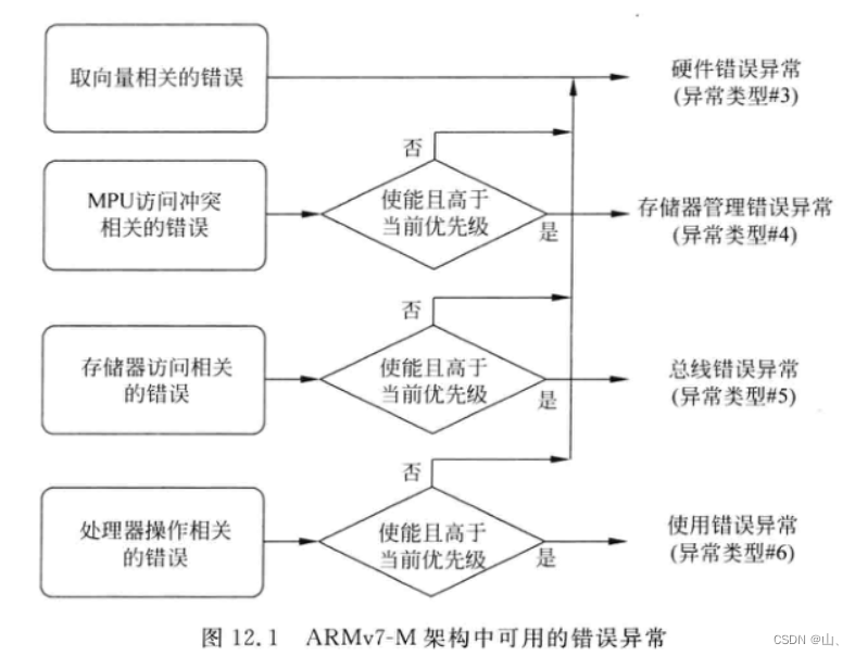
Anomalies are divided into different types according to their causes , For example, bus error exception 、 Use error exception 、 Hardware error, exception, etc . When an exception occurs , The program will jump to the corresponding exception service function to execute .
1、 Undefined instruction exception
Undefined instruction , There are no defined instructions ,CPU Unrecognized instructions . When CPU An exception will occur when an undefined instruction is executed .
for example :
DCD 0xffffffff ; This is an exception instruction
When CPU When the above instructions are executed , Exceptions will occur , Then the program will jump to the corresponding exception interrupt function to execute . In the corresponding abnormal interrupt function, you can print information for debugging .

Interrupt function :
void HardFault_Handler(void)
{

	puts("HardFault_Handler is running !\r\n");
}
void UsageFault_Handler(unsigned int * stack)
{

	puts("UsageFault_Handler is running !\r\n");
}
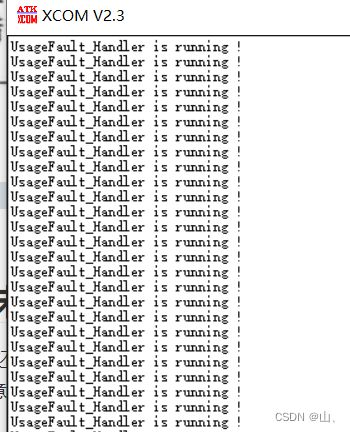
experimental result :

We can see two abnormal phenomena :
1、 Execution is HardFault_Handler Function instead of UsageFault_Handler function , According to the exception vector table, you can see , When an undefined instruction occurs, the corresponding function should be UsageFault_Handler.
2、 The interrupt function has been executed repeatedly , It is generally believed that it should be implemented once .
Why execute HardFault_Handler
ARM Cortex-M3 And Cortex-M4 The authoritative guide introduces :

To sum up, we can see that , The default interrupt function for all exceptions is HardFault_Handler, This explains why HardFault_Handler Function .
Undefined instruction belongs to " Processor operation related errors ", If not enabled "Usage Fault", It will trigger "Hard Fault". So make it possible Usage Fault.
Can make Usage Fault:
Find the official documents :core_cm3.h, It defines one SCB Structure .

SCB Is the system control block , It contains many registers , Among them SHCSR Is to enable Usage Fault Of . In the red box below is SCB The base address .
Here are the enablers in the authoritative guide Usage Fault Operation process :

Enable code :
void usage_fault_enable(void)
{

	SCB_Type * SCB = (SCB_Type *)SCB_BASE_ADDR;
	SCB->SHCSR |= (1<<18);	// Set the first 18 individual bit
}
experimental result :
You can see , The exception is UsageFault_Handler function .
Why do I keep calling UsageFault_Handler function
Check the manual and see SCB There is a register in CFSR.


See from above ,CFSR Of bit16 position , When he was 1 When , Stored in the stack PC Value points to the undefined instruction that caused the current exception .
I said before cortex-M3 in , Before function jump , The hardware automatically saves the values of some registers , Among them, there is the return address value , At this time, the return address is the address of the undefined instruction .
When the abnormal interrupt function is completed , The program will run again from the undefined instruction that just caused the exception , This will cause the program to execute an abnormal interrupt function . That's why UsageFault_Handler The function will be called repeatedly .
So you need to modify the value of the return address in the function , Give Way PC Point to the next instruction .

C Functions cannot be passed SP, So write assembly function to pass stack pointer SP, And then call C Function change SP Medium PC value .
	DCD     UsageFault_Handler_asm         ; Usage Fault Handler
UsageFault_Handler_asm PROC
	MOV R0,SP	; hold SP Stack pointer passed to R0, call C function stack It points to SP
	B 	UsageFault_Handler	; Out of commission BL, because BL Will change LR Register value , Abnormal function jump LR What is saved is a special value
void UsageFault_Handler(unsigned int * stack)
{

	puts("UsageFault_Handler is running !\r\n");
	stack[6] += 4;	//PC Point to the next instruction
}
The return address is saved in SP Of the 7 block , Corresponding stack Namely stack[6].
I said before , The first parameter of the function is saved in R0 in , So in the assembly function SP Pass to R0, If C The function has two parameters, such as void UsageFault_Handler(volatile unsigned int i,unsigned int * stack)
At this time, we should put SP Save in R1 in .
MOV R1,SP
Output results :
You can see UsageFault_Handler One execution is over .
Other online materials say that for UsageFault_Handler Function also needs to be cleared CFSR register , There are two operations in the function 1、 eliminate usage fault;2、 Give Way PC Point to the next instruction .
void UsageFault_Handler(unsigned int * stack)
{

	SCB_Type * SCB = (SCB_Type *)SCB_BASE_ADDR;
	puts("UsageFault_Handler is running !\r\n");
	// eliminate usage fault
	SCB->CFSR = SCB->CFSR;
	//PC Point to the next instruction
	stack[6] += 4;
}
But after the above experiment, I found that it is not clear usage fault That is not to carry out SCB->CFSR = SCB->CFSR;, The program can still run normally . It may need to be cleared in order to deal with some situations , I won't clear up the specific reasons .
Set the value of some registers in the assembly file , When an abnormal interruption occurs in the verification ,R0 The data of such registers is saved in SP in .
ldr r0,=0
ldr r1,=0x11111111
ldr r2,=0x22222222
ldr r3,=0x33333333
ldr r12,=0x44444444
ldr lr,=0x55555555
DCD 0xffffffff	; Undefined instruction
void UsageFault_Handler(unsigned int * stack)
{

	SCB_Type * SCB = (SCB_Type *)SCB_BASE_ADDR;
	puts("UsageFault_Handler is running !\r\n");
	put_s_hex("R0 = ",stack[0]);
	put_s_hex("R1 = ",stack[1]);
	put_s_hex("R2 = ",stack[2]);
	put_s_hex("R3 = ",stack[3]);
	put_s_hex("R12 = ",stack[4]);
	put_s_hex("LR = ",stack[5]);
	put_s_hex("PC = ",stack[6]);
	put_s_hex("PSR = ",stack[7]);
	stack[6] += 4;
}
Output results :

You can see , The value in the above register is indeed stored on the stack and passed to C Function .
stay keil In the middle of debug debugging :

Note here SP The value of the stack pointer , Look at the memory 0x2000FFE0 Data in :

You can see the front 6 One is the value we set , The seventh return address is 0x08000068.

You can see DCD 0xffffffff The address of 0x08000060+4+4=0x08000068.
Open the disassembly file , You can also see DCD 0xffffffff The address of the instruction is 0x08000068.
explain SP It does save R0 And so on .
2、 SVC abnormal
SVC( Request management call ) Commonly used in OS Use in , Use SVC The instruction deliberately triggers an exception , So as to call the exception handling function of the kernel , Put the program into the kernel .
Use SVC The mechanism can be used to realize the access of application tasks to system resources API.

See from the authoritative guide SVC Instruction usage , In the kernel, corresponding functions can be executed according to parameters .

In the operating system , For example, all kinds of RTOS perhaps Linux, Will use SVC The instruction deliberately triggers an exception , This causes the exception handling function of the kernel to be called , Then use the kernel services .
experiment :
Add SVC Instructions :
SVC #1
Exception service function :
void SVC_Handler(void)
{

	puts("SVC_Handler is running !\r\n");
}

You can see , Yes SVC_Handler function , And this exception function is executed only once , Different from the undefined instruction exception above .


You can see that the return address in the stack is 0x08000052.

Open the disassembly file , You can see 0x08000052 It is SVC The next instruction of the exception instruction . So after the exception service function is executed, it will return to the next instruction of the exception instruction to continue execution .
About SVC The specific contents of the exception can be queried Cortex-M3、M4 Authoritative guide 10.3 chapter .
3、SysTick abnormal
SysTick It also belongs to an anomaly , This timer is embedded in CPU Upper , For different types of SCM , As long as the internal CPU It's the same type , that SysTick It's all the same , About SysTick The program code can be consistent , There is no need to modify .
About SysTick The relevant content is in the previous SCM learning notes 7–SysTick Timer is introduced , No more detailed explanations here .

SysTick The main registers of are the three in the red box above .
SysTick->LOAD: Reload value
SysTick->VAL: Current count
SysTick->CTRL: Enable timer 、 Set the trigger edge 、 Enable abnormal interruption, etc
experiment :
use SysTick Realization LED flashing :
I didn't set the system clock here , So the system clock is the default HSI Input , That is to say 8MHz.
Reload value calculation formula :
S y s T i c k − > L O A D = T i m e / ( 1 / C l k ) SysTick->LOAD = Time/(1/Clk) SysTick−>LOAD=Time/(1/Clk)
among Time It's a cycle , The unit is seconds , That is, every Time Time produces an interrupt ,Clk It's the clock . This way SysTick every other 1s Create an interrupt ,LOAD The value is 1/(1/8000000) = 8000000. For other timers, it can also be calculated in this way .
You can see from the picture above SysTick Register address of , Here is a brief introduction .
1、SysTick->CTRL


You can see from the top , This register has 4 individual bit have access to .
| bit0 | Can make SySTick | 0: Do not enable ;1: Can make |
|---|---|---|
| bit1 | Can make SySTick interrupt | 0: Do not enable ;1: Can make |
| bit2 | choice SySTick Clock source | 0:AHB/8:1:AHB |
| bit16 | Count completion flag bit | When SySTick Count to 0, Set up 1 |
2、Sys Tick->LOAD

This register is used to store the reload value , When you count to 0 when , Will automatically LOAD The value of the register is loaded in VAL In the register .
3、SysTick->VAL

VAL The register holds SysTick The current count , Yes VAL Register for write operations , This register will be cleared and CRTL In register bit1 Sign a .
When the counter is down systick->VAL Reduced to 0 when , The following events will happen :
1、systick->CTRL Of TICKINT Bit enable systick abnormal 、ENABLE After the bit is enabled, it is set by the hardware , But if the suspended state is set again because the required processing task takes too long , It needs to be removed systick Suspended state of SCB->ICSR |= 1<<25, Prevent it from hanging again .
Load again LOAD It's worth it VAL Decrement the count again :systick->VAL = systick->LOAD
systick->CTRL Of bit16 Location 1, If this bit is read , Will be automatically cleared
Program code :
void SystemTickInit(void)
{

	unsigned int * pSys_CTRL = ( unsigned int * )(0xE000E010);
	unsigned int * pSys_LOAD = ( unsigned int * )(0xE000E014);
	unsigned int * pSys_VAL = ( unsigned int * )(0xE000E018);
	unsigned int * pSys_CALIB = ( unsigned int * )(0xE000E01C);

	*pSys_VAL = 0;	// Empty VAL Registers also put CTRL The flag bit in is cleared
	*pSys_LOAD = 8000000 - 1;	// Set the count reload value to 8000000 - 1, Count to 0 when 1s
	*pSys_CTRL |= (1<<2) | (1<<1) | (1<<0);	// choice AHB The clock , To interrupt , Can make SysYick
}
void SysTick_Handler(void)
{

	static int led_state = 0;
	unsigned int * pGPIOOdr = ( unsigned int * )(0x40010C00 + 0X0c);
	SCB_Type * SCB = (SCB_Type *)SCB_BASE_ADDR;

	if(led_state == 0)
	{

		*pGPIOOdr |= (1<<0);// Light on
	}
	else
	{

		*pGPIOOdr &= ~(1<<0);// The light goes out
	}
	led_state = ~led_state;
	// When the exception enters the active state ,  Its suspension position is cleared by hardware ( However, if the suspended state is set again because the required processing task takes too long, it needs to be cleared )
	//SCB->ICSR |= (1<<25); // Clear exceptions , If not cleared , Function return will execute the exception function again
}
5、 ... and 、 interrupt
Some knowledge about interruption can be seen in SCM learning notes 8– Keys and external interrupts , There is an introduction . The following is not a detailed explanation of some of the things introduced before .
Interrupt is also an exception , Exceptions cannot be masked , Interrupts can be masked . SCM has many interrupts , Here is STM32F103 The vector table in the startup file , The upper one is abnormal , Below is the interruption .

Previously introduced ,Cortex-M3、M4 The interrupt vector table of is a function , Jump to the corresponding function when an exception or interrupt occurs . and A7 Different ,A7 The vector table of corresponds to instructions .
1、 Interrupt hardware framework
The complete structure of an interrupt consists of three parts :
1、 Interrupt source : The interrupt , Send an interrupt signal
2、 Interrupt controller : All interrupt signals are gathered in the interrupt controller , It is uniformly controlled by the interrupt controller , Set interrupt priority , Select the interrupt with the highest priority and send it to CPU. The interrupt controllers of different cores are also different , such as Cortex-M3、M4 called NVIC,Cortex-A7 Medium is GIC.
3、CPU: Every time an instruction is executed , Will judge whether there is an interruption .CPU There is also a register inside , Used to set enable / No interruptions , It is the main switch of interrupt processing .
2、STM32F103 interrupt
So if you want to configure a complete interrupt, you need to configure the interrupt controller and CPU Internal registers , If the interrupt source has other controllers, it needs to be configured separately , such as STM32F103 Of GPIO interrupt , They have an external interrupt controller EXTI.

With GPIO For example , To realize the external interrupt function , Configure the above three parts .
One 、 Interrupt source configuration
1、GPIO Control register : Responsible for selecting a GPIO Pin as the input source of interrupt .
Each group GPIO Yes 0-15 common 16 One pin , Use 4 A register controls . Each group GPIO The same pin of is on an interrupt line , Only one... Can be used at a time , That is to use PA0 As interrupt source , that PX0(X=B-G) Cannot be used as an interrupt source .

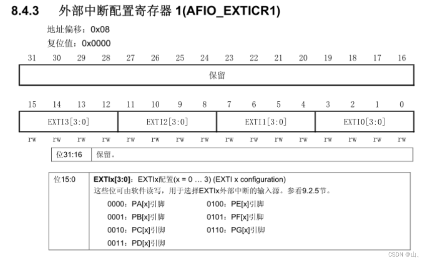
AFIO_EXTICR1 be responsible for PIN0-PIN3 The control of , Empathy AFIO_EXTICR2 be responsible for PIN4-PIN7 The control of ,AFIO_EXTICR3 be responsible for PIN8-PIN11 The control of ,AFIO_EXTICR4 be responsible for PIN12-PIN15 The control of .
2、EXTI controller : Be responsible for setting whether the trigger edge is triggered by the rising edge or the falling edge 、 Enable or mask interrupts .

There are external interrupt lines 20 individual , except 16 individual GPIO Of , There are four other , No introduction here .
From the register description ,EXTI_IMR Which one? bit Position as 1, Then the corresponding interrupt will be enabled .

From the register description ,EXTI_RTSR Which one? bit Position as 1, Then the corresponding interrupt will be selected as the rising edge trigger interrupt mode .

From the register description ,EXTI_FTSR Which one? bit Position as 1, Then the corresponding interrupt will be selected as the rising edge trigger interrupt mode .
These are the main registers , There are several other registers , We will not introduce them one by one here .
This interrupt source configuration is complete , Underneath NVIC To configure .
Two 、NVIC To configure
NVIC Be responsible for assigning priority to each interrupt , At the same time, select the interrupt with the highest priority among all interrupts and send it to CPU.
NVIC The related registers are as follows :
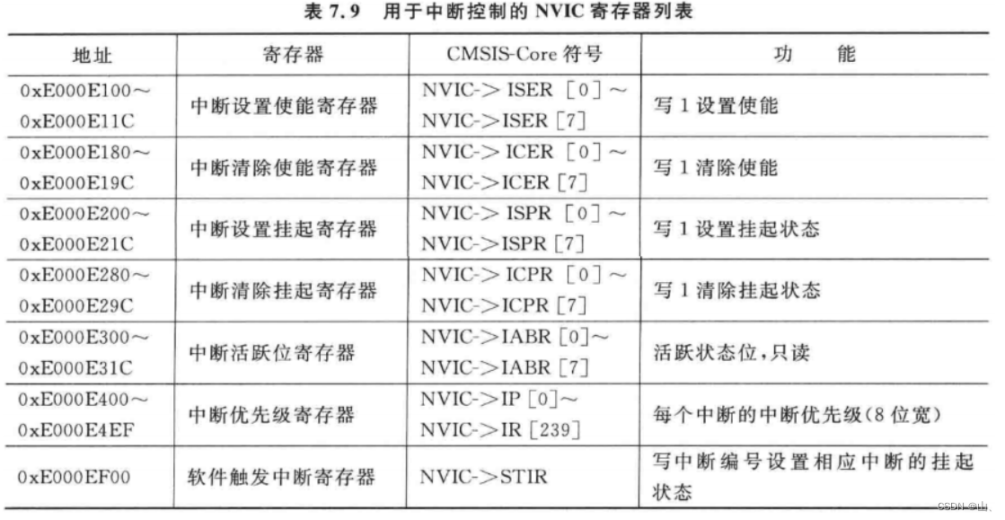
The main ones are :ISER、ICPR.
ISER Registers are used to set interrupt enable , Write 1 To interrupt .

ICPR Registers are used to clear the suspended state of interrupts .
Be careful : These registers above are not 1 individual , But there are many similar arrays . such as ISER Include ISER0,ISER1,ISER2. Each bit in it corresponds to an interrupt .


3、 ... and 、CPU
CPU There is a master switch for all interrupts inside , If this is not enabled bit, Then the interruption will not work .

You can see ,CPU In the internal special register ,FAULTMASK、PRIMASK、BASEPRI It's about the exception register .
PRIMASK
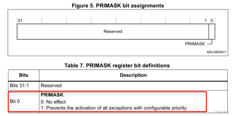
This register has only bit0 It works , Set up 1 Mask all interrupts with configurable priority . That is, clear enable interrupt .
These instructions can be used in the assembly file to set it :
CPSIE I  ;  eliminate PRIMASK, To interrupt
CPSID I  ;  Set up PRIMASK, No interruptions
 perhaps :
MOV R0, #1
MSR  PRIMASK R0  ;  take 1 write in PRIMASK Disable all interrupts
MOV R0, #0
MSR PRIMASK, R0  ;  take 0 write in PRIMASK Interrupt all
FAULTMASK

FAULTMASK Registers are also only bit0 It works , Set up 1 Will shield all exceptions , except NMI.
These instructions can be used in the assembly file to set it :
CPSIE F  ;  eliminate FAULTMASK
CPSID F  ;  Set up FAULTMASK
 perhaps :
MOV R0, #1
MSR  FAULTMASK R0  ;  take 1 write in FAULTMASK No interruptions
MOV R0, #0
MSR FAULTMASK, R0  ;  take 0 write in FAULTMASK To interrupt
BASEPRI
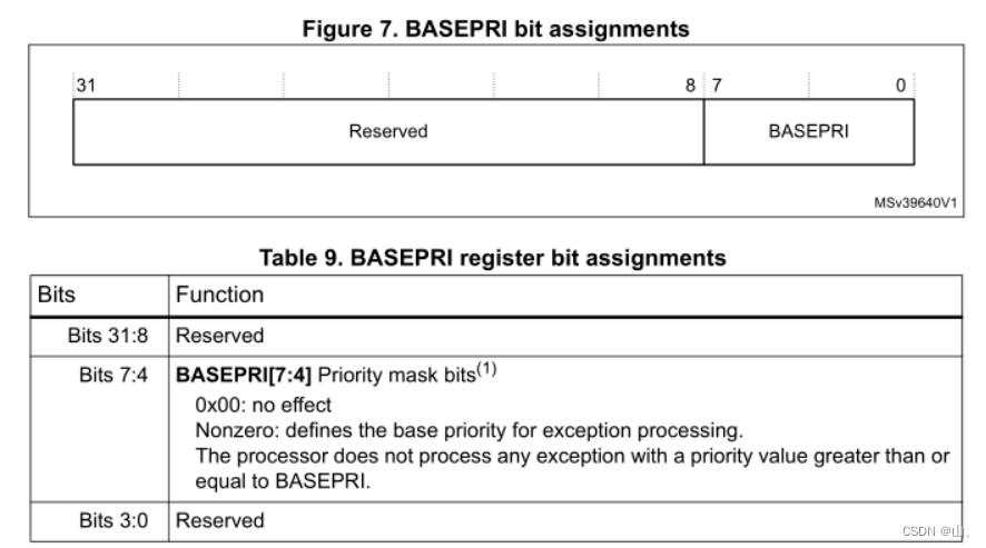
BASEPRI The register only has bit4-bit7 It works , Mask interrupts in a specific priority range according to the value of this register .
for example bit4-bit7 The value is 0x60, Then the shielding priority is higher than 0x60 The interrupt , Only allow priority lower than 0x60 Interrupt execution of . Write 0 Then this register does not work .
These instructions can be used in the assembly file to set it :
MOVS R0, #0x60
MSR BASEPRI, R0   ;  Prohibit priority higher than 0x60 The interrupt
MRS R0, BASEPRI   ;  Read BASEPRI
MOVS R0, #0
MSR BASEPRI, R0    ;  Cancel BASEPRI shielding
6、 ... and 、 Key interruption experiment
After the above introduction, we can know the process of configuring interruption .
1、 Set interrupt source :
Using keys KEY1–PA0 Pin . Set up GPIO The input mode .
Enable external interrupt line EXTI0, choice PA0 Is the interrupt source .
EXTI Set and select the double edge trigger mode , to open up PA0 Interrupt request .
typedef struct
{

	volatile unsigned int EVCR;
	volatile unsigned int MAPR;
	volatile unsigned int EXTICR[4];
	volatile unsigned int RESERVED;
	volatile unsigned int MAPR2;
}AFIO_REG_TYPE;
typedef struct
{

	volatile unsigned int IMR;
	volatile unsigned int EMR;
	volatile unsigned int RTSR;
	volatile unsigned int FTSR;
	volatile unsigned int SWIER;
	volatile unsigned int PR;
}EXTI_REG_TYPE;
void key_init()
{

	AFIO_REG_TYPE	*AFIO_EXTI = (AFIO_REG_TYPE*)(0x40010000);

	unsigned int * pAPB2En = ( unsigned int * )(0x40021000 + 0x18);
	unsigned int * pGPIOACrl = ( unsigned int * )(0x40010800 + 0x00);
	*pAPB2En |= (3<<2);// Turn on GPIOA The clock
	*pGPIOACrl |= (1<<2);// Set up PA0 The input mode
	AFIO_EXTI->EXTICR[0] &= 0x0f;// Set up PA0 Is the interrupt source
}
void exti_init(void)
{

	EXTI_REG_TYPE	*EXTIStu = (EXTI_REG_TYPE*)(0x40010400);

	EXTIStu->IMR |= (1<<0);		// to open up PA0 Interrupt request
	EXTIStu->FTSR |= (1<<0);	// Falling edge trigger
	EXTIStu->RTSR |= (1<<0);	// Rising edge trigger
}
2、NVIC Set up
Enable the corresponding interrupt .
typedef struct
{

    volatile unsigned int ISER[8];
    volatile unsigned int RESERVED0[24];
    volatile unsigned int ICER[8];
    volatile unsigned int RSERVED1[24];
    volatile unsigned int ISPR[8];
    volatile unsigned int RESERVED2[24];
    volatile unsigned int ICPR[8];
    volatile unsigned int RESERVED3[24];
    volatile unsigned int IABR[8];
    volatile unsigned int RESERVED4[56];
    volatile unsigned int IP[240];
    volatile unsigned int RESERVED5[644];
    volatile unsigned int STIR;
}NVIC_Type;
void nvic_init(void)
{

	NVIC_Type *pStuNvic = (NVIC_Type*)(0xE000E100);

	pStuNvic->ISER[0] |= (1<<6);//EXTI0_IRQHandler The interrupt function number is 22,22-15=7, The corresponding is bit6
}
In the assembly EXTI0_IRQHandler Interrupt function , You can see that there is 15 Exceptions ,EXTI0_IRQHandler He is abnormal #22, stay ISER The middle is bit6.

__Vectors       DCD     0
                DCD     Reset_Handler              ; Reset Handler
                DCD     0                ; NMI Handler
                DCD     HardFault_Handler          ; Hard Fault Handler
                DCD     0          ; MPU Fault Handler
                DCD     0           ; Bus Fault Handler
                DCD     UsageFault_Handler_asm         ; Usage Fault Handler
                DCD     0                          ; Reserved
                DCD     0                          ; Reserved
                DCD     0                          ; Reserved
                DCD     0                          ; Reserved
                DCD     SVC_Handler             ; SVCall Handler
                DCD     0           ; Debug Monitor Handler
                DCD     0                          ; Reserved
                DCD     0             ; PendSV Handler
                DCD     SysTick_Handler            ; SysTick Handler
                ; External interrupt
				DCD     0            ; Window Watchdog
                DCD     0             ; PVD through EXTI Line detect
                DCD     0          ; Tamper
                DCD     0             ; RTC
                DCD     0           ; Flash
                DCD     0             ; RCC
                DCD     EXTI0_IRQHandler           ; EXTI Line 0
3、CPU Interrupt enable
CPU Enable to operate in assembly file , The specific methods are introduced above .
; Can make CPU interrupt
	CPSIE I
After the above three steps of interruption, the configuration is completed , Let's look at the experimental phenomenon .
void EXTI0_IRQHandler(void)
{

	unsigned int * pGPIOIdr = ( unsigned int * )(0x40010800 + 0x08);
	if((* pGPIOIdr) & (1<<0) == 1)	// Press the key
	{

		puts("KEY1 has been pressed! \n\r");
	}
	else
	{

		puts("KEY1 released! \n\r");
	}
	// Clear flag bits
	exti_clear_flag(6);
	nvic_clear_flag(6);
}
experimental result :

Be careful : If the flag bit is not cleared , Will always call EXTI0_IRQHandler Interrupt service function . When clearing the flag bit, the most important thing is to clear the flag bit of the interrupt source, that is EXTI The mark of a .
边栏推荐
- B tree and b+ tree
- 1000个Okaleido Tiger首发上线Binance NFT,引发抢购热潮
- Easyexcel export case (only you can't think of it)
- HCIP网络类型,ppp会话,数据链路层协议
- 国产MCU和SOC崛起但特殊领域仍落后
- Hcip day 10 notes
- Free learning machine learning transaction resources
- SCM learning notes 6 -- interrupt system (based on Baiwen STM32F103 series tutorials)
- Copying readable paths is not easy
- MGRE experiment
猜你喜欢


随机推荐
Kotlin基础从入门到进阶系列讲解(基础篇)关键字:suspend
简单GAN实例代码
Review questions of polymer synthesis technology
好大夫问诊-俞驰-口腔信息
MGRE experiment
HCIP第一天笔记
Rip (notes of the second day)
Network type (notes on the third day)
Rip --- routing information protocol
Research on retinal vascular segmentation based on GAN using few samples
Create.Img image file
cmake之add_dependencies
Why can't HMI panels of botu V17 and below connect with CPUs of 1500 firmware version 2.9 or 1200 firmware version 4.5?
128. 最长连续序列
OSPF (fourth day notes)
Research on retinal vascular segmentation based on GAN using few samples
Interview question: what are the differences between ArrayList and LinkedList
Hcip day 9 notes
Copying readable paths is not easy
Solve the problem that the double click of Google Chrome browser doesn't respond and can't be started (friendly testing)