当前位置:网站首页>Axi low power interface
Axi low power interface
2022-06-24 11:26:00 【FPGA silicon agriculture】
AXI Low power interface
Interface signal
CSYSREQ
The system clock controller pulls down CSYSREQ To request the device to enter a low power state ;
The system clock controller is pulled up CSYSREQ To request the device to exit the low power state .
CSYSACK
The equipment is pulled down CSYSACK To respond to the request of the system clock controller to enter the low power state ;
Equipment is raised by pulling CSYSACK To respond to the request of the system clock controller to exit the low power state .
CACTIVATE
CACTIVATE Used to indicate whether the device needs a clock signal .
sequential
The device accepts a low power request

stay T1 moment , The system clock controller drives CSYSREQ by LOW, To request peripheral devices to enter a low power state . After the peripheral recognizes the request , It performs its power down sequence , stay T2 It drives all the time CACTIVATE For low . And then in T3 moment , Peripheral drive CSYSACK by LOW, It indicates that it has entered a low-power state .
Device rejects low power request
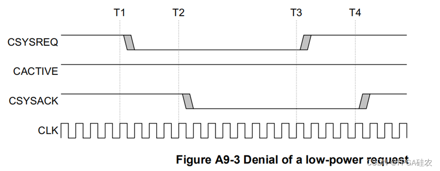
stay T1 moment , The system clock controller drives CSYSREQ by LOW, To request peripheral devices to enter a low power state . stay T2 when , Peripherals remain CACTIVATE For the high , And pull down CSYSACK To respond , Indicates that the request is rejected . stay T3 moment , The system clock controller drives CSYSREQ Exit low power state for high . stay T4 moment , The periphery is driven by CSYSACK Respond to high , To exit the low power state .
Exit the low power state
System clock controller or Peripherals Can request to exit from the low power state .
System clock controller initiated exit
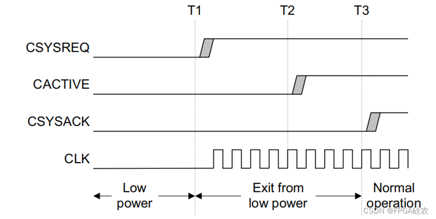
stay T1 moment , The system clock controller drives CSYSREQ For the high , Request to exit the low power state , Then enable the clock . The peripheral recognizes CSYSREQ It's high , Perform its power on sequence , And in T2 drive CACTIVATE For the high , To show that it needs a clock signal . then , Peripheral devices are driven by CSYSACK For the high , stay T3 Low power exit request completed at .
Peripheral initiated exit

stay T1 moment , Peripheral drive CACTIVATE For the high , Indicates that it requires a clock signal . then , The system clock controller must restore the clock . stay T2 when , The system clock controller drives CSYSREQ For the high . The peripheral device completes its exit from the low power state , And drive CSYSACK High to complete the exit of low power state .
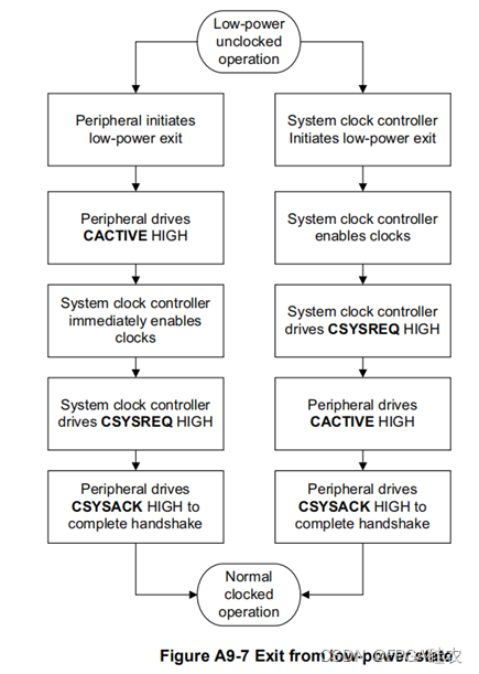
flow chart
Flow chart for entering low power state

Flow chart for exiting the low power state
边栏推荐
- Google Earth engine (GEE) - how to add a legend in the map panel
- [深度学习][pytorch][原创]crnn在高版本pytorch上训练loss为nan解决办法
- Base64 decoding method three ways for non professionals
- Does the depth system work?
- 历史上的今天:图灵诞生日;互联网奠基人出生;Reddit 上线
- Apple's legendary design team disbanded after jobs refused to obey cook
- Istio best practice: graceful termination
- How to export only the titles in word documents? (i.e. delete all the text contents and keep only the title) stop B
- What characteristics should a good design website have?
- PF_ Ring ZC | high speed traffic processing dpdk alternative
猜你喜欢

软件测试 对前一日函数的基本路径测试

@RequestBody注解

qt -- QTabWidget 中支持拖拽TabBar项

Déplacer Tencent sur le cloud a guéri leur anxiété technologique

Shell脚本(.sh文件)如何执行完毕之后不自动关闭、闪退?
![[graduation season · attacking technology Er] three turns around the tree, what branch can we rely on?](/img/0a/0ebfa1e5c1bea6033b538528242252.png)
[graduation season · attacking technology Er] three turns around the tree, what branch can we rely on?

Qt: judge whether the string is in numeric format

【本周六活动】.NET Day in China

计组_cpu的结构和工作流程

腾讯开源项目「应龙」成Apache顶级项目:前身长期服务微信支付,能hold住百万亿级数据流处理...
随机推荐
Nxshell session management supports import and export
软件测试 对前一日函数的基本路径测试
Jetpack Compose 教程之 从一开始就投资于良好的导航框架将帮助您在之后节省大量的迁移工作
Nacos source code - configure automatic update
今日睡眠质量记录76分
Many of my friends asked me what books and online classes I recommended. This time, I contributed all the materials that I had been hiding for a long time (Part 1)
Tencent's open source project "Yinglong" has become a top-level project of Apache: the former long-term service wechat payment can hold a million billion level of data stream processing
2D 照片变身 3D 模型,来看英伟达的 AI 新“魔法”!
Which is a good CAD drawing software? How to select good software
Shell脚本(.sh文件)如何执行完毕之后不自动关闭、闪退?
[Flink source code practice (I)] add a rest API to Flink
Reliable remote code execution (1)
Understanding of homogeneous coordinates
《opencv学习笔记》-- 矩阵归一化 normalize()函数
How to export only the titles in word documents? (i.e. delete all the text contents and keep only the title) stop B
What characteristics should a good design website have?
Influence of DEX optimization on arouter lookup path
Déplacer Tencent sur le cloud a guéri leur anxiété technologique
"Write once, run at all ends", Qualcomm released AI software stack!
SwiftUI Swift 内功之 Swift 中的属性观察者 didSet 与 willSet