当前位置:网站首页>Electronics: Lesson 011 - experiment 10: transistor switches
Electronics: Lesson 011 - experiment 10: transistor switches
2022-06-25 07:58:00 【acktomas】
experiment 10: Transistor switch
Now that you know the characteristics of capacitors , I will explain another basic element : The transistor . After learning the working principle of transistors , You can explore how capacitors and transistors work together .
Items needed
- Breadboard 、 Connecting line 、 Wire nippers 、 Wire stripper 、 A multimeter
- 2N2222 The transistor 1 individual
- 9 V Batteries and connectors 1 individual
- resistor :470 Ω 2 individual 、1 MΩ 1 individual
- 500 kΩ Fine tuning potentiometer 1 individual
- Universal LED 1 individual
Finger experiment
I will use 2N2222 The transistor , It has been the most widely used semiconductor component ( It was developed by Motorola in 1962 The invention of , Since then, a variety of styles have been developed , It is still in production ).
Motorola 2N2222 The patent for the transistor expired a long time ago , So any company can produce its own transistors . Some transistors are covered with black plastic , Other transistors are packaged in small metal cans . I'm drawing 2-23 These two types of transistors are shown in . These two kinds of transistors can achieve our goal . however , Please pay attention to the precautions I raised about the part number ( Refer to the necessary tools in this chapter : Transistor section ). Number is the same as 2N2222 The transistors are different , You need to use the right model .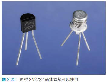
Turn the transistor 、LED And a 470 Ω The resistor of is inserted into the bread board , Pictured 2-93 Shown . determine LED The long pin of is left , follow + No . Then make sure that the flat side of the transistor faces to the right . If you rarely use a metal can transistor , Then the pins protruding from the metal can should point down and to the left .

Be careful , The green and yellow wires in the figure have an extra section of insulation removed . If you are using a pre cut connector , Then you need to straighten one end of each connecting wire , So they can be laid on the surface of the bread board .
Here is the interesting part . Pictured 2-94 Shown , Press your finger on the bare metal core of the green and yellow wires , Observe at the same time LED. If nothing happens , Just slightly wet your fingers , Do it again . The harder you press ,LED The brighter . Transistors amplify the small current flowing through your fingers .

Be careful : Don't use both hands
If the current just flows through your fingers , The fingertip switch demonstration experiment is safe . You can't even feel the current , Because this is only provided by a small battery 9 V Direct current . But if you hold down a wire with the fingers of one hand , The fingers of the other hand press the other wire , That's not good . So the current can flow through your body . The current is very small , This circuit won't hurt you , But you must not get into the habit of letting electricity flow from one hand to the other . and , When you touch the wire , Don't let it pierce the skin . This also means that you cannot apply voltage to any jewelry that has pierced the skin .
The secret of finger experiment

Look at the graph. 2-95, It draws the connecting line inside the bread board , The connecting line not connected to the circuit is omitted . Be careful , The lead at the bottom of the transistor is connected with the... Through the bread plate LED Connect , And then through 470 Ω The resistor of is connected to the negative bus . therefore , There is enough current flowing out of the transistor , Can light up LED.
Where does this current come from ? There is indeed some current flowing through the skin of your finger into the central pin of the transistor , But the current is too small , Not bright enough LED.
There is only one other explanation left . There is a third pin at the top of the transistor , Connected to the positive bus , Current flows through this pin into the transistor . then , This current in some way , Controlled by a small current flowing through your finger into the middle pin of the transistor .
chart 2-96 This principle is explained .

By the way , This phenomenon is quite different from the response of the capacitor in the previous experiment . The capacitor passes only a short pulse of current , And the transistor controls the steady current .
Basic knowledge of : The transistor
In this study , The element you use is a bipolar transistor . There are two types of , Namely NPN The type and PNP type . You used NPN The type a transistor consists of three layers of silicon , Two of them N The layer contains excess negative charge carriers . The third layer of silicon ——P The layer is sandwiched between two N Between layers , Contains excess positive charge carriers . I won't go into too much detail about how transistors work at the atomic level , Because in this book , I am more interested in the function of the transistor , Not the theory of how it works . You can find relevant information in any technical tutorial or online resources .
NPN The three pins of a bipolar transistor are called collectors 、 Base and emitter , Pictured 2-97 Shown .
- When NPN When the base voltage of A-type transistor is slightly higher than the emitter voltage , The transistor allows a positive current to flow from the collector , Out of the emitter .
- In this way , The very small current flowing from the base of the transistor can control the large current flowing through the collector .

PNP The function of type a transistor is similar to NPN Type a transistor is the opposite . When the base voltage is slightly lower than the emitter , It allows negative current to flow from the collector , Out of the emitter . In circuit ,PNP T-type transistors are sometimes more convenient , But it is not widely used . In this book , I can't use them .
chart 2-98 It shows NPN Four representations of the A-type transistor on a circuit diagram . They all work the same . Letter C、B、E Remind you , These connections correspond to the collector 、 Base and emitter .

chart 2-99 It shows PNP Four circuit diagram representation methods of type a transistor . They all work the same .
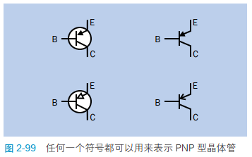
PNP The type and NPN Type a transistors are easily confused , But there is a simple way to identify them .NPN The arrow in the symbol points outward , Never look inward . therefore , You can put NPN Imagine as never pointing in( Never point inward ) Abbreviation .
Add potentiometer
To better understand how transistors work , We need a more controllable component than the fingertips . I think potentiometer can meet this requirement , But not the large potentiometer you used before . It is recommended that you use the trimmer potentiometer , Pictured 2-22 Shown . Although potentiometers vary in shape and size , But they all have three pins . The functions of these pins are the same as the three pins of the large potentiometer you have used before . The middle pin is always connected to the sliding plate inside the potentiometer , The other two pins are respectively connected with both ends of the resistive track inside the potentiometer . Here are the basic rules you must follow :
Insert the potentiometer into the bread board , Each pin must be connected to a row of separate holes on the bread board .
chart 2-100 Clarified this rule . At the top of the graph , I drew the top view of three potentiometers , Including multi turn potentiometer , Although I don't recommend , But you may need it one day . Pins are not visible from above , I drew their positions , Just as you can see them through components . The positions of the pins are different , But there are always three , Their vertical distance shall be 1/10 Inch .

At the bottom of the picture , Two Yes The example of works well , Because each pin is connected to a different row of pins on the bread board . Two No The example of does not work , Because a pair of pins will be short circuited by a wire inside the bread board .
Understand the basic knowledge of potentiometer , You should be able to add one to the transistor circuit 500 kΩ The potentiometer of , Pictured 2-101 Shown . Connect the power supply , Use a small screwdriver to turn the potentiometer clockwise all the time , Then rotate it counterclockwise . Be careful , If at first LED Is completely extinguished , Then you have to turn the screw on the potentiometer slightly , So it can light up .

Take a look at the picture 2-102 Circuit diagram in , Its circuit connection is the same as that of bread board , But its layout is more simple to understand .

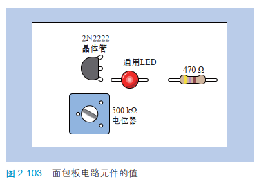
chart 2-103 Shows the value of each component .
The potentiometer is connected between the positive bus and the negative bus . From this point of view , We call it a voltage divider . When the sliding piece is at one end of the track , It is directly connected with the positive pole of the power supply . At the other end of the track , It is directly grounded ( Negative pole ). In the middle , It divides the voltage . This is how potentiometers are usually used , Used to provide a full range of various voltage values .
I just said that , When you just move the slide of the potentiometer from the negative pole to the positive pole ,LED It's not lit up . It's just because LED Not getting enough electricity ? Not entirely. .
The bipolar transistor subtracts part of the electric energy , In return for its services . The base voltage is higher than the emitter voltage ( Usually about 0.7 V), It will respond . In this mode , The transistor is forward biased .
chart 2-104 This general concept is explained .

Voltage and current
You already know , The voltage at the base of a bipolar transistor controls the output of the transistor . Does this mean that the transistor amplifies the voltage ?
You can explore for yourself . Take out the multimeter , Set it to measure voltage , Fix the black probe with the negative bus on the bread board with a test lead , Pictured 2-105 Shown . Touch the emitter pin of the transistor with the red pen , Record the voltage , Then touch the base pin with the red pen . I guarantee that the voltage at the emitter is lower than that at the base .
Adjust the potentiometer to different positions , Measure again . No matter how you change the voltage on the base pin , The voltage on the emitter pin is always lower .

This is because 470 Ω Does the resistor not provide enough resistance between the emitter and the negative bus of the transistor ? Did it pull the voltage down ?
Let's find out the answer . Remove LED and 470 Ω resistor , Connect a between the emitter and the negative pole of the transistor 1 MΩ The resistor . Large resistance does not cause much effect , The voltage at the emitter will still be lower than the voltage at the base .
If you have the patience to measure the current flowing into the base and out of the emitter , You will find that they are very different . You must set the multimeter to measure milliampere current , And connect it to each position to be measured in the circuit . remember , The current must flow through the multimeter to measure .
I want to tell you what you will find : This transistor amplifies the current flowing into the base , Magnification greater than 200. This factor is called the... Of the transistor ȕ value , From this we get a basic fact :
Bipolar transistors amplify current , Do not amplify the voltage .
Now I will summarize the related knowledge of bipolar transistors , For your future reference .
Basic knowledge of :NPN The type and PNP A summary of the knowledge of type a transistors
A transistor is a semiconductor device , It is between conductor and insulator . Its effective internal resistance will vary according to the voltage applied to the base .
All bipolar transistors have three pins : Collector 、 Base and emitter , Abbreviated on the manufacturer's data sheet C、B and E, These pins are marked for you .
- NPN A-type transistor is excited by the forward voltage of the base relative to the emitter .
- PNP A-type transistor is excited by the negative voltage of the base relative to the emitter .
In the passive state , Both transistors block the flow of current between the collector and emitter , Like an open single pole single throw switch .( In fact, transistors allow very little current to flow through , It is called leakage current .)
In the circuit diagram , The direction of the transistors may vary . The emitter may be at the top , The collector is below , Or vice versa . The base is most likely on the left , It may also be on the right , It depends on how the circuit diagram drawing personnel draw conveniently . Be sure to observe the arrow of the transistor symbol , Look in which direction it is facing , The transistor is NPN still PNP transistor . If the connection is wrong , You will damage the transistor .
Transistors come in many sizes and structures . The construction of many transistors is difficult to judge , Which wire is connected to the emitter 、 Collector or base . You may need to consult the manufacturer's data sheet .
If you forget which pins of the transistor are , Many multimeters can help you distinguish the emitter 、 Collector and base . A multimeter usually has four holes , Mark respectively E、B、C and E. When you insert the emitter pin of a transistor E hole , Base pin insertion B hole , The collector pin is inserted C hole , The multimeter will show the transistor β value . If you insert in another direction , The reading of the multimeter will be unstable or no indication , Or the reading is zero , Or much less than expected ( Almost always less than 50, And usually less than 5).
Be careful : Fragile components !
Transistors are easily damaged , Once damaged, it cannot be recovered .
- Do not connect the power supply directly between any two pins of the transistor , Otherwise, the transistor will be burned by excessive current .
- Be sure to use resistors and other elements to limit the current between the collector and emitter of the transistor , In the same way Protect LED.
- Do not apply reverse voltage .NPN The collector voltage of a transistor must be higher than the base voltage , The base voltage is higher than the emitter voltage .
Background knowledge : The origin of the transistor
Although some historians trace the origin of the transistor to the invention of the diode ( Diodes allow current to flow in one direction , And hinder the flow of reverse current ), But the first fully functional utility transistor is 1948 John from Bell Laboratories • Buddy (John Bardeen)、 William • Shockley (William Shockley) And Walter • Brattain (Walter Brattain) Developed .
Shockley is the leader of the team , He has a vision , The potential importance of solid state switches is foreseen . BARDIN is a theorist , And Badin was actually the inventor of the transistor . Before success , This is a very productive team . After the invention of the transistor , Shockley began to play tricks , Put the patent right of transistor under your own name . When he informed the team members of the news , Naturally, , Everyone was very unhappy .
A widely circulated publicity photo also helped . In the photo , Shockley sat in front of a microscope in the middle , It seems that he has finished the manufacturing work , And two other members stood behind him , It implies that their role is less important . A copy of this photo appears in Electronics On the cover of the magazine ( See the picture 2-106). actually , Shockley as supervisor , It rarely appears in the laboratory where the transistor was invented .

The productive cooperation team soon disintegrated . Bratan requested a transfer to at & T (AT&T) Go to the laboratory . Bardeen went to the University of Illinois to study theoretical physics . Shockley finally left Bell Labs , Founded Shockley semiconductor company , This company is the predecessor of Silicon Valley , But his ambition goes beyond the technology of his time . His company has never produced a profitable product .
Shockley's eight employees finally betrayed him , They left the company , Set up your own business —— Xiantong Semiconductor Co (Fairchild). The company achieved great success in the manufacture of transistors and later integrated circuit chips .
Basic knowledge of : Transistors and relays
NPN The type and PNP One limitation of type a transistors is : They need to realize their functions under the power supply , Relays are different , It can be switched on and off without any power input .
The relay also provides more switching options . The status of different relays can be normally open 、 Normally closed , Or lock at any position .
The relay may contain a double throw switch , There are two switches to select ; It may also include double pole switches , It can form ( Or disconnect ) Two completely independent connections . Single transistor devices cannot provide double throw or double pole switching functions , But you can also design more complex circuits to simulate this function .
chart 2-107 The characteristics of transistor and relay are compared .
Whether to use relays or transistors will depend on each specific application .
The theoretical part is finished . Now? , We can use an interesting 、 Useful , Or a transistor with both ?
We can do experiments 11 《 Light and sound 》!
边栏推荐
- [little knowledge] PCB proofing process
- Buckle 78: subset
- 电子学:第013课——实验 14:可穿戴的脉冲发光体
- 【补题】2021牛客暑期多校训练营6-n
- 力扣 272. 最接近的二叉搜索树值 II 递归
- 【视频】ffplay 使用mjpeg格式播放usb摄像头
- 电子学:第010课——实验 8:继电振荡器
- 【补题】2021牛客暑期多校训练营4-n
- Tips on how to design soft and hard composite boards ~ 22021/11/22
- Solving some interesting problems with recurrence of function
猜你喜欢

使用Adobe Acrobat Pro调整PDF页面为统一大小

How to resize an image in C #

Modular programming of LCD1602 LCD controlled by single chip microcomputer

静态网页服务器

Solving some interesting problems with recurrence of function

CAN总线工作状况和信号质量“体检”

How to select lead-free and lead-free tin spraying for PCB? 2021-11-16

深度学习系列48:DeepFaker

挖掘微生物暗物质——新思路

产品经理专业知识50篇(四)-从问题到能力提升:AMDGF模型工具
随机推荐
VSCode很好,但我以后不会再用了
洛谷P6822 [PA2012]Tax(最短路+边变点)
Anaconda based module installation and precautions
剑指offer刷题(中等等级)
Modular programming of LCD1602 LCD controlled by single chip microcomputer
取消word文档中某些页面的页眉
C#控件刷新
Startup, shutdown and restart of Oracle and MySQL on Linux
@The difference between resource and @autowired annotation, why recommend @resource?
C control refresh
洛谷P1073 [NOIP2009 提高组] 最优贸易(分层图+最短路)
1464. maximum product of two elements in an array
Cifar-10 dataset application: quick start data enhancement method mixup significantly improves image recognition accuracy
Share the process requirements for single-layer flexible circuit board
27. 移除元素
剑指offer刷题(简单等级)
c#磁盘驱动器及文件夹还有文件类的操作
剑指 Offer II 027. 回文链表
CAN总线工作状况和信号质量“体检”
CAN透传云网关CANIOT,CANDTU记录CAN报文远程收发CAN数据