当前位置:网站首页>SCM learning notes 5--stm32 clock system (based on Baiwen STM32F103 series tutorials)
SCM learning notes 5--stm32 clock system (based on Baiwen STM32F103 series tutorials)
2022-07-24 01:20:00 【Mountains】
The fifth chapter STM32 The clock system
Section 1 STM32 Clock tree
Clock is of great significance to single chip microcomputer , Single chip computer can't work without clock ,STM32 Any peripheral of without a clock , Can't work , So if you want a peripheral to work , The first step is to turn on his clock .
because STM32 It's very complicated , There are many peripherals , But in actual use, only a limited number of peripherals will be used , And different peripherals need different clock frequencies , Some high speed , Some low speed . So in order to reduce power consumption , Improve the anti-jamming ability , More complicated MCU All of them adopt a variety of clock sources to solve these problems .
from STM32 From the clock tree , I will STM32 Our clocks fall into three categories :
One 、 Crystal oscillator clock , That is, the system clock in the red box is input to the source clock , Used to configure the system clock , share 4 individual .
1、 Internal high speed clock (High Speed Internal clock signal)HSI:MCU High speed clock signal provided internally ,RC oscillator ,8MHz frequency . There is no additional cost when using , But the accuracy is relatively poor .
2、 External high-speed clock (High Speed External clock signal)HSE: Provided by external crystal oscillator circuit , The input frequency range is required to be 4-16MHz. High accuracy , But it will increase the cost .
3、 External low speed clock (Low Speed External clock signal)LSE: Provided by external crystal oscillator circuit , It's the frequency input 32.768KHz. Commonly used in RTC Real time clock .
4、 Internal low speed clock (Low Speed Internal clock signal)LSI: Internal low speed RC The oscillator provides , frequency 40KHz. The watchdog clock can only be LSI, meanwhile LSI It can also be used as RTC The clock source of .
Be careful :HSE The pin of is OSC_OUT and OSC_IN These two pin chips are led out independently , It can be connected to external crystal oscillator circuit ; and LSE The pin of OSC32_IN and OSC32_OUT The two pins are not independent , But in PC14 and PC15 On ,OSC32_IN–>PC14 ; OSC32_OUT–>PC15
about STM32F103 Series of MCU, Both need a high-speed clock source and a low-speed clock source , Internal clock source saves cost , You don't need to design your own clock circuit ; External clock source improves accuracy , You need to design your own clock circuit .
Two 、 In the green box The system clock , It's the working clock of the chip .
3、 ... and 、 All in the blue box Peripheral clock .

I said before , Any peripheral must turn on its clock before it works , So how to turn on his clock .
It can be seen from the analysis above that , The peripheral clock is attached to APB1 and APB2 Upper , and APB1、APB2 yes AHB From bus frequency division ,AHB The clock of the bus is directly connected with the system clock , So turn on the system clock , The peripheral clock will turn on . So where does the system clock come from .
In the second quarter System clock source
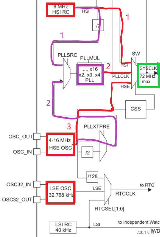
The picture above shows , The system clock source has three paths in total :
1、 Directly from the internal high-speed clock , The system clock is 8MHz. If the program does not configure the system clock , After the system is powered on , The default system clock source is the internal high-speed clock , That is to say 8MHz.
2、 Input through PLL .
As you can see from the picture above , The clock source of PLL also has two parts , One is from the internal high-speed clock 2 frequency division , The other is from the external high-speed clock .
From the internal high-speed clock 2 frequency division , PLL input clock is 4MHz, Through frequency doubling , The maximum output is 4*16 = 64MHz.
From external high-speed clock ,(STM32F103 The external high-speed clock of is 8MHz) PLL direct input 8MHz, Through frequency doubling , The maximum output is 8*9 = 72MHz. Because the maximum value of the system clock is 72MHz, So the PLL here is the largest 9 frequency doubling .
3、 Directly from the external high-speed clock , The system clock is 4-16MHz.
In the third quarter Peripheral clock source
above-mentioned , All peripherals are attached to APB1 and APB2 On the bus ,APB1 and APB2 Your clock comes from AHB frequency division , and AHB The clock comes from the system clock frequency division .
in other words , After getting the system clock , In the configuration AHB and APB1、APB2 The pre frequency division coefficient of can determine the peripheral clock .

The fourth quarter, Real time clock and independent watchdog clock sources
The clock source of the real-time clock has three paths .
1、 By external high-speed clock 128 Frequency division .
2、 External low speed clock ( Usually choose this ).
3、 Internal low speed clock .
The clock of the independent watchdog only comes from the internal low-speed clock .
Section 5 To configure STM32 The system clock
5.1 Configure the system clock process
After the introduction above , We are right. STM32 The source of all clocks in has been clearly recognized , Next, we can configure the clock .
Configuring the clock is generally divided into the following steps :
1、 Determine the source of the system clock , yes HSI still HSE Or PLL input .
2、 Determine the relevant frequency division 、 Frequency doubling coefficient —— Here the system clock is set .
3、 To configure AHB、APB1、APB2 The division coefficient of —— Here, the peripheral clock is set .
After these three steps ,STM32 The clock of is configured , What clock is needed later , Just call the corresponding function to start the corresponding clock .
In general , We all want the system to work at the maximum allowable clock frequency , So generally STM32F103 The clock is configured as 72MHz. It said , The system clock should be configured as 72MHz, It can only be achieved by PLL output 72MHz Working frequency of .
In this mode , The system clock and peripheral clock of the single chip microcomputer can reach the maximum value allowed by the system , Therefore, the system clock is usually configured in this way .

5.2 Use HAL Library configuration clock
HAL Library SystemInit Functions are not like the standard library SystemInit Function to initialize and configure the clock , So use HAL library We must write our own clock configuration function .
5.2.1 Related structures
stay HAL In the library , Two structures are needed to configure the system clock .

On the left RCC_OscInitTypeDef The structure describes the crystal oscillator source . The members inside are used to indicate the state of the external high-speed clock 、 frequency division 、 Internal high-speed clock status and oscillator type and PLL Properties of PLL . This structure is to set the clock source of the clock tree and the relevant information of the PLL , In the red box below .

The structure on the right RCC_ClkInitTypeDef It describes the type of open clock , Is it the system clock or AHB The clock is still APB1、APB2 The clock of ; also AHB、APB1、APB2 Clock prescaler , The part in the SCM clock tree is the part in the red box in the figure below .

5.2.2 Correlation function
stay HAL In the library , The functions used for clock configuration are generally as follows .
Unmarked 5 Functions are generally used less , No introduction here .
5.2.3 Configure the system clock code
This is the code provided by Baiwen .

Be careful :HAL_RCC_ClockConfig(RCC_ClkInitTypeDef *RCC_ClkInitStruct, uint32_t FLatency) The second parameter is to set FLASH Reading and writing speed , CPU The higher the frequency is. , The larger this parameter can be selected .STM32 Of FLASH In the manual , About FLASH_ACR The register of LATENCY Description of bit :
0 wait state if 0MHz < SYSCLK <= 24MHz
1 wait state if 24MHz < SYSCLK <= 48MHz
2 wait state if 48MHz < SYSCLK <= 72MHz
The following is the clock configuration process described earlier , Write your own clock configuration code .
About RCC_OscInitTypeDef Members of the structure , You don't need to assign all the configuration , Keep the default value . For unnecessary things, such as HSE As the input source of the system clock , that HSI The configuration of does not need to be assigned as off , Keep the default value , They are all closed by default . The same is true for other structures , When some default values are the values we need to set , There is no need to assign values to the structure members .
So we just need to set up 1、 The crystal oscillator source is HSE;2、HSE State on ;3、HSE1 frequency division ( stay STM32F103 in , Only 1 Frequency division, so it's OK not to set )4、PLL The input source is HSE;5、PLL open ;6、PLL by 9 frequency doubling . The sequence is shown in the figure below .

Configure according to the above figure ,HSE1 It's divided into 8MHz As PLL Input ,PLL9 Frequency doubling is 72MHz As a system clock ,AHB1 The clock is the system clock 1 Divide the frequency to get , yes 72MHz,APB1 The clock is AHB The clock 3 frequency division , by 36MHz,APB2 The clock is AHB The clock 1 Frequency division comes from 72MHz.
The system clock = 72MHz;
AHB The clock = 72MHz;
APB1 The clock = 36MHz;
APB2 The clock = 72MHz;
call HAL Library function , See if the actual clock is the same as the theoretical value .


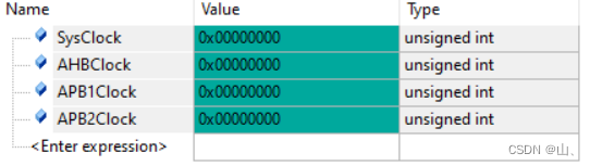


You can see , The actual value of the four clocks is the same as the theoretical value of the configuration .
边栏推荐
- 128. 最长连续序列
- 罗克韦尔AB PLC RSLogix5000中的位指令使用方法介绍
- 使用C语言和libcyaml库解析yaml配置文件
- Create database table db.create in flask project_ all()
- High voltage technology test questions and answers
- LVS load balancing scheduling principle and configuration method
- HCIP第六天笔记
- 【FreeSwitch开发实践】专栏简介
- 数字签名技术简介
- Skywalking distributed system application performance monitoring tool - upper
猜你喜欢
Navicat for MySQL installation tutorial

Explanation and induction of polymer physics terms

HCIP第六天_特殊区域综合实验

为什么博途V17及以下的HMI面板不能与1500固件版本2.9或1200版本4.5 的CPU建立连接?

Sublime text 3 Chinese + add common plug-ins

OSI、TCP/IP(A1)

HCIP实验

Use of crawler request library 2
Kubernetes deployment dashboard (visual interface)

HCIP第十二天笔记
随机推荐
HCIP第九天笔记
Deep understanding of collaborative process
The problem that all values are the same occurs after golang for range traverses and assigns values to the dictionary
OSPF(第四天笔记)
Data warehouse construction - ods floor
cnpm 执行时卡住应该怎么解决?
复制可读路径不好使
Matlab extracts the original data in the illustrations of the paper - fig2data tool
HCIP第三天笔记
HCIP第七天笔记
Openresty模板实时渲染 lua-resty-template
Preprocessing instruction define, do you really understand?
MGRE实验
C language force deduction question 53 of the largest subarray sum. Dynamic programming and divide and conquer
HCIP第六天笔记
网络类型(第三天笔记)
Broadcast, multicast, unicast
The flare project celery uses the pits encountered in redis sentinel
Leetcode -- 136. a number that appears only once
小熊派简介和环境搭建