当前位置:网站首页>TP-LINK 1208 router tutorial (2)
TP-LINK 1208 router tutorial (2)
2022-06-24 11:15:00 【An operation and maintenance young man】
TP-LINK 1208 Router usage
Official documents
https://service.tp-link.com.cn/public/customer/pc/im-main.html?source=detail
Official document II
WARWVR The detailed configuration guide and FAQ reference for series routers :
https://smb.tp-link.com.cn/service/detail_article_4748.html

How to view the product model and hardware version ?
The model and hardware version of the product are the only identification that defines the product , There are two ways to view :
Method 1 : Check on the sticker
On the back of the product shell ( Or the bottom 、 The side ) Find the location of the sticker . Labeled model ( or Model) Product model , Serial number (Serial Number or SN code ) In a column ,Ver The following number is the hardware version . With TL-WDR6300 V6.0 For example , See below :

Method 2 : View in the management interface
If the product has WEB Management interface , Please use the administration address Log in to the product management interface see . Generally, you can view the product model and hardware version at the place where the software is upgraded , Here's the picture :

If the hardware version is not directly displayed in the local upgrade interface , Click the local upgrade button , View the hardware version in the pop-up interface , Here's the picture :

Scheme 1
How to set up a router ?
**1.** Connect the line
Connect the operator's broadband network cable to the router WAN Mouth or WAN/LAN mouth , Internet computer connected to router LAN On the mouth .

After the line is connected , If WAN The indicator light corresponding to the port is not on , It indicates that there is a problem with the line connection , Please check that the network cable is firmly connected or try to change another network cable . Please refer to : When the network cable is connected, the indicator light does not light up ?
2. Set up a router to access the Internet
(1) Open the browser , Clear the address bar and type tplogin.cn, And set the login password of the router in the pop-up window ,( The length of the password is 6-15 Bit interval ), This password is used to manage the router in the future ( Login screen ), Please take good care of . Here's the picture

If you cannot log in to the router management interface , Please refer to
http://service.tp-link.com.cn/detail_article_1679.html
(2) After successful login , The router will automatically detect the Internet access mode , Here's the picture :

(3) According to the detected Internet access mode , Fill in the corresponding parameters of the Internet access mode :
- If the Internet access mode is detected as “ Automatic access to IP Address ”, Click next , No need to change the way you surf the Internet , Here's the picture :

- If the Internet access mode is detected as “ Broadband dial-up Internet access ”, You need to enter the broadband account and password provided by the operator , After input, click next to set , Here's the picture :

(4) Set the wireless name and wireless password of the router , After setting up , Click on “ complete ” Save configuration . Be sure to remember the wireless name and wireless password of the router , It is necessary to connect the router wirelessly in the future .

Be careful : The wireless name is recommended to be set to letters or numbers , Try not to use Chinese 、 Special characters , Avoid that some wireless clients do not support Chinese or special characters, resulting in search failure or inability to connect .
(5) Setup completed , Wait for the configuration to be saved :

Option two
First step 、 Line connection
1、 Connect the front-end broadband line to the router WAN mouth , The Internet computer is connected to any router LAN mouth .

The second step 、 Log in to router management interface
Open the browser , Clear the address bar and enter the management address at the bottom of the router tplogin.cn( Some models of routers may not have Can't log in through the domain name , Please refer to the login address marked on the bottom of the router ), In the pop-up setting management password interface , Set up 6~15 Bit management password , Click on < determine >, Log in to router management interface .

The third step 、 choice WAN The number of mouths
Follow the quick setup wizard to set up WAN The number of mouths , That is, the number of external network lines .
[ Failed to transfer the external chain picture , The origin station may have anti-theft chain mechanism , It is suggested to save the pictures and upload them directly (img-UxutBIqv-1655450234871)(https://tianmingqing.oss-cn-hangzhou.aliyuncs.com/aike/image-20220613174736757.png)]
Step four 、 choice WAN Internet access by mouth
Select according to broadband type PPPoE、 static state IP Or dynamic IP How to surf the Internet . Take broadband dial-up Internet access as an example , stay Select... In the corresponding setting box PPPoE dial , Enter the broadband account and password provided by the operator , And confirm the password of the account Enter correctly , Click on < next step >.

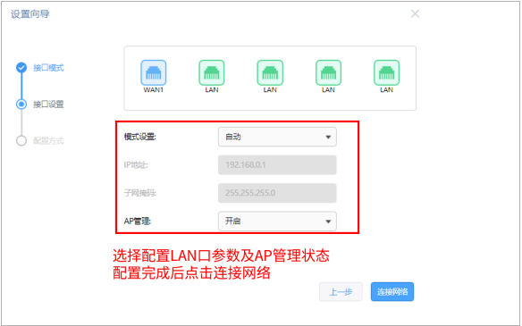
Step five 、 choice WAN Internet access by mouth
Set according to the network planning LAN Oral IP Address and subnet mask , Also select settings AP The management status is on or off close . After setting, click < Connect to the network >, Wait until the router is configured and connected to the network .
Step six 、 Choose configuration mode
After the network connection is unblocked , Select the normal configuration mode , Click on < next step >.

Step seven 、 Wireless network settings
Enter wireless network settings , Set the wireless network name and password , After setting, click < next step >

After setting up , The router will send messages separately 2.4G Signals and 5G The signal .
Step eight 、 Confirmation information

thus , The router has been set up . After the computer is connected to the router, it can directly open the web page and surf the Internet , No longer use the computer Of " broadband connection " To dial the number .
WVR/WAR Series router AP How to use management
Official document
https://smb.tp-link.com.cn/service/detail_article_4693.html
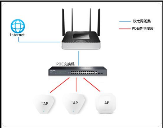
Demand analysis
An enterprise uses wireless AP Conduct wireless networking , Centralized wireless management through the main router AP. It is necessary to set up the employee wireless network for the use of enterprise employees .
Setup method
1. Enable AP management function
Log in to the router interface , Click on “AP management >AP Set up >AP Set up ”, Check “ Enable AP management function ”, The display type is selected as “ On-line AP equipment ”, The currently online... Will be displayed in the list AP, Confirm that the router has found AP, And can be used to AP Conduct management , Here's the picture :

【 reminder 】 If part AP Can't find , Please make sure the AP The mode switch of has been turned to FIT Pattern 、 Check at the same time AP The network cable with the switch has been connected .
2. edit AP Related parameters of
stay AP Click Edit... In the list , The number of terminal access can be set 、 Channel, transmission power and other parameters , Here's the picture :

Two 
Click the upgrade button , It can also be used for AP Upgrade in batches , Here's the picture :


【 reminder 】 Cannot offline AP Upgrade and switch LED Operation of the lamp .
3. Set up AP Wireless networks for
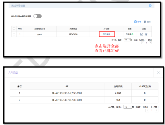
Click on “AP management > Wireless network settings ”, If automatic synchronization of router wireless settings is enabled , Then access AP when ,AP The wireless signal set by the router will be transmitted . You can also click  by AP Set up the wireless network manually , Here's the picture :

【 remarks 1】: If you create a new wireless network name, it needs to be bound to all AP, Please select “ Automatically bind all AP” The option to , Then all connected AP Will be automatically bound to the wireless network , There is no need to perform the operation in step 4 below ; If you create a new wireless network name that is only binding part AP, Please select “ Select... Manually AP” The option to , And proceed to step 4 below AP Bind operation .
【 remarks 2】: If the client devices connected wirelessly in your wireless network do not need to access each other through the LAN , Recommended Opening “ Internal isolation ” Options , It can improve the stability of wireless network ; If there is a need for mutual access , Proposed closure “ Internal isolation ” Options .
【 reminder 】 If automatic synchronization of router wireless settings is enabled , And set up the wireless network manually ,AP The synchronization router and the manually set wireless signal will be transmitted at the same time .
4. RF binding
(1) If the wireless service is set to manual selection AP, Clickable “ binding AP”, Then check the items to be bound AP And RF , Here's the picture :


(2) Check the items to be bound first AP And RF , Click on < determine > that will do . When the binding is complete , Click on “ Show all ” You can see all the bound AP.


5. RF tuning
After the wireless configuration is completed , Use the router's built-in RF tuning function , It can be done to AP Wireless channel and transmit power are automatically adjusted , To ensure a good wireless experience .
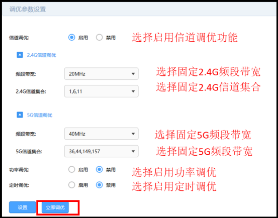
(1) Click on “AP management > RF tuning ”, Conduct AP Band bandwidth and channel adjustment , Click tune now :

(2) Optionally enable power tuning and timing tuning , The parameters can be adjusted according to the actual situation :
[ Failed to transfer the external chain picture , The origin station may have anti-theft chain mechanism , It is suggested to save the pictures and upload them directly (img-ZAkqgr4p-1655450234875)(https://tianmingqing.oss-cn-hangzhou.aliyuncs.com/aike/image-20220613164536641.png)]
Wireless configuration settings and AP RF tuning is complete , all AP Can be launched at the same time Office The wireless signal of , For enterprise employees .
thus ,WVR/WAR Series routers AP Management settings complete .
How to set automatic restart ?
3.2.1  Application Introduction
 When the router works for a long time , The router system overhead may be too large and cause network exceptions , It's like a computer ,
 Working for a long time may cause the system response to be slower and slower , Just restart it . However, due to the placement of routers
 Or other factors , It is inconvenient to restart manually . At this time, the enterprise router “ Automatic cleaning ” The function is implemented within a specified time period
 Let the router restart automatically .
In this paper, WAR/WVR Configuration steps of automatic cleaning function of series enterprise wireless routers .
Demand is introduced
A small enterprise needs to set up a router in the early morning of every Sunday 3 Click to restart automatically .
First step 、 Confirm the router system time
The time when the router automatically restarts is determined by the system time when the router is running , So set the automatic restart function Make sure that the router has obtained the correct system time . adopt “ System tools >> Set the time ” Confirm whether the current time is correct :

 The system time of the router is through connecting to the Internet  NTP  Automatically obtained by the server , If the front-end line cannot be connected to the Internet
 Or some operators' line faults cannot be recovered from  NTP  Server acquisition , Then you need to choose to set the system time manually . Such as
 If the system time of the computer host currently logged into the router management interface is correct , You can also directly select to obtain the management host
 Time .

The second step 、 Set the automatic restart time
stay “ System tools >> Equipment management >> Automatic cleaning ”, Set the time for automatic restart , Click on < determine >, Add rules such as Next :

remarks : It is generally recommended to set the restart time when the network utilization is not high . thus , Auto cleanup setup complete , The router can restart automatically at the set time point .
Demand is introduced
An enterprise uses WAR/WVR Series router , Next to the layer 3 switch , The switch is divided into VLAN10, Need to achieve Router LAN The terminal of the network segment can be connected with the terminal under the layer 3 switch VLAN10 The terminals of the network segment conduct mutual visits .

Setup method
Log in to the router interface , Click on “ Advanced features >> Routing settings >> Static routing ”, Click on < newly added >, Set it up .

thus , The static routing function is set , Router LAN The terminal of the network segment can be connected with the terminal under the layer 3 switch VLAN10 network The terminals of the segment have conducted mutual visits .
Virtual Server Setup Guide
Application Introduction
The enterprise builds various servers internally , Such as FTP The server 、WEB The server 、 Mail server 、 Monitoring servers, etc . These servers are not only open to intranet users , Internet users also need to access through the Internet . fictitious The server function can map the intranet servers to Internet, So as to realize the access of the external network . In this paper, WAR/WVR Configuration steps of virtual server function of series enterprise wireless routers .

Demand is introduced
 A small enterprise needs to open its web server to the Internet . This requirement is realized through the virtual server function . User network parameters
 as follows :

Setup method
First step 、 Confirm that the server is set up successfully Before setting up the virtual server , Please be sure to confirm the following operations

The second step 、 Add virtual server rule
 Log in to the management interface of the router , Click on “ Advanced features >> Virtual server ”, Click on < newly added >, Add the following mapping rule ,  And click the < determine >

 Be careful : Because broadband operators may block  80、8080  Etc , Therefore, it is recommended that external ports do not use these ports ,
 The external port can be set to  9000  Ports above .

The added entries are as follows :

thus , Virtual server rule setting is complete .
The third step 、 Internet access server
According to the above settings , Users of the external network access through the browser WEB The server , The form of the visit is as follows :

Be careful : The specific access form shall be subject to the actual server requirements . If your broadband is not static IP Address , Can be in “ dynamic DNS” Apply for a domain name account in and log in to the account in the router Number , After successful login, use the domain name and open port to access the server .
NAT-DMZ Function setting guide
Application Introduction
 The enterprise builds various servers internally , Such as  FTP  The server 、WEB  The server 、 Mail server 、 Monitoring servers, etc .
 These servers are not only open to intranet users , Internet users also need to access through the Internet .NATDMZ  The function can map the intranet server to  Internet, So as to realize the access of the external network .
 In this paper,  WAR/WVR  Series of enterprise wireless routers  NAT-DMZ  Configuration method of functions .

Demand is introduced
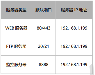
 A small business needs to  WEB  The server 、FTP  The server 、 The monitoring server is open to the Internet , And hope that both internal and external networks can
 Access by using the protocol default port . The user network parameters are as follows :
Setup method
First step 、 Confirm that the server is set up successfully

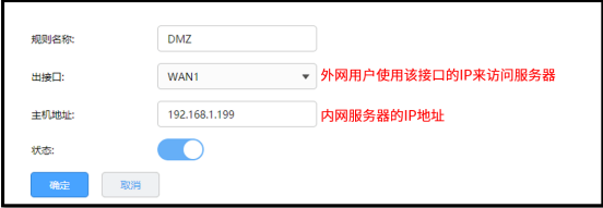
The second step 、 add to NAT-DMZ The rules
 Log in to the management interface of the router , Click on “ Advanced features >> Virtual server >>NAT-DMZ”, Click on < newly added >, add to
 The following rules , And click the < determine >.


 Be careful : Because broadband operators may block  80、8080  Etc , Therefore, it is necessary to confirm that the port used is at the current width
 Under the belt line, it can be accessed on the Internet .
thus ,NAT-DMZ Setup completed , The terminal can use the default port of the protocol to access both inside and outside the network .
Wireless settings
many SSID Setup Guide
Application Introduction many SSID The main purpose is to enable wireless terminals to access the network in different security authentication and encryption methods , Let a wireless AP can To achieve multiple AP In order to achieve SSID Different functions .

Demand is introduced
 An enterprise has built a wireless network , Want to achieve : Set up two wireless networks for the use of the market department and other departments , And market
 The Department and other departments cannot exchange visits by wireless 、 However, LAN sharing can be realized among the same departments .
Setup method
First step 、 Set up wireless network of marketing department
 In the router interface , Click on “ Wireless settings >> Wireless network settings ”, The wireless network settings of the marketing department are as follows :

 Be careful : If enabled “ Internal isolation ”, The wireless terminals connected to the wireless network will not be able to communicate with each other .

The second step 、 Set up wireless networks for other departments
Click on “ Wireless settings >> many SSID”, Click on < newly added >, Set up wireless networks for other departments , as follows :

Finally, it is enabled , many SSID The list is as follows :
 remarks : Dual band enterprise wireless router  5G  More frequency bands  SSID  Setting method and  2.4G  The same as .
 thus , many  SSID  Setup completed , Employees in different departments of the enterprise connect to their own wireless networks to access the Internet .

Wireless bridge (WDS) Setup Guide
Application Introduction
 At present, wireless network has become the preferred solution for families and small and medium-sized enterprises , However, due to the environmental degradation of wireless signals
 Less serious , Use a wireless router for wireless network coverage , There will be a signal difference 、 The data transmission rate is less than that of the user
 demand 、 There are even signal blind spots . We can use the wireless router  WDS  function , Increase the wireless network
 Coverage 、 Improve long-distance wireless transmission rate .
Demand is introduced
 The existing wireless signal of an enterprise has the problem of signal blind spot in some areas , For more convenient office , Therefore, one set of No
 Wire router for wireless bridging , Expand wireless coverage . The wireless parameters of the existing wireless signal are as follows :

Setup method
First step 、 Specify the same wireless channel as the front end
 remarks : All bridging settings are completed on the secondary router , The primary router does not need to be set .
 In the router interface , Click on “ Wireless settings >> Advanced settings ”, Set the channel to be consistent with that of the front-end wireless router , Merging
 blow < preservation >, Here's the picture :

The second step 、 Turn on the wireless bridging function and bridge the signal
 In the router interface , Click on “ Wireless settings >> Wireless network settings ”, Enable wireless bridging . The bridging method is < sweep
 Trace bridging >, Click on < scanning >, Scan to the front-end wireless signal , And click the < Connect >, Here's the picture :

Fill in the wireless password of the front-end wireless signal , And click the < Connect >, Here's the picture :

Bridging complete , The wireless bridging page prompts that the bridging is successful , Here's the picture :

The third step 、 close DHCP The server
Click on “ Basic settings >>LAN Set up >>DHCP service ”, close , Here's the picture :

Step four 、 modify LAN mouth IP Address
 Click on “ Basic settings >>LAN Set up ”, modify LAN mouth IP The address and the front-end router address are in the same network segment but do not conflict .
 For example, the address of the front-end router is  192.168.1.1, The modified  LAN  mouth  IP  The address is  192.168.1.2.


 thus , The wireless bridge function is set . Enterprise employees can use the network after successfully connecting after searching for signals .

frequently asked questions
Q1、 How to set to realize wireless roaming ?
 After setting according to the above method , It just realizes wireless bridging . To achieve wireless roaming , After completing the above settings ,
 It is also necessary to set the wireless signal name and wireless password of the sub router to be the same as that of the front-end router . Setup method : Click on “ nothing
 Line setting > Wireless network settings ”, Modify the wireless network name and wireless password .

AP Management Setup Guide
Application Introduction
WVR/WAR  Series of enterprise wireless routers can be easily managed  FIT  Mode of  AP, by  AP  Unified wireless configuration
 The Internet . In this paper,  WVR/WAR  Series Router Management  AP  Configuration method of .
Demand is introduced
 An enterprise uses wireless  AP  Conduct wireless networking , Centralized wireless management through the main router  AP. It is necessary to set up employee wireless network
 The network is for the use of enterprise employees .
Setup method
First step 、 Enable AP management function
 Log in to the router interface , Click on “AP  management >>AP  Set up >>AP  Set up ”, Check < Enable  AP  management function >, display
 The display type is selected as < On-line  AP  equipment >, The currently online... Will be displayed in the list  AP, Confirm that the router has found  AP,
 And can be used to  AP  Conduct management , Here's the picture :

 notes : If part  AP  Can't find , Please make sure the  AP  The mode switch of has been turned to  FIT  Pattern 、 Check at the same time  AP  And switch
 The network cable of has been connected .

The second step 、 edit AP Related parameters of
stay AP Click Edit... In the list , The number of terminal access can be set 、 Channel, transmission power and other parameters , Here's the picture :


 Click on < upgrade > Button , It can also be used for  AP  Upgrade in batches , Here's the picture :

 notes : Cannot offline  AP  Upgrade and switch  LED  Operation of the lamp .


The third step 、 Set up AP Wireless networks for
 Click on “AP  management >> Wireless network settings ”, If automatic synchronization of router wireless settings is enabled , Then access  AP  when ,
AP  The wireless signal set by the router will be transmitted . You can also add settings  AP  Wireless networks for , Here's the picture :

explain :
If you create a new wireless network name, it needs to be bound to all AP, Please select “ Automatically bind all AP” The option to , Then the connected station
Yes AP Will be automatically bound to the wireless network , There is no need to perform the operation in step 4 below ; If you create a new wireless network name
Call it binding only AP, Please select “ Select... Manually AP” The option to , And proceed to step 4 below AP Bind operation .
If the client devices connected wirelessly in your wireless network do not need to access each other through the LAN , Recommended Opening “ Inside
Partial isolation ” Options , It can improve the stability of wireless network ; If there is a need for mutual access , Proposed closure “ Internal isolation ” Options .
If automatic synchronization of router wireless settings is enabled , And set up the wireless network manually ,AP The synchronization router will be launched at the same time
And manually set wireless signals .
Step four 、 RF binding
1、 If the wireless service is set to < Select... Manually  AP>, Clickable < binding  AP>, Then check the items to be bound  AP  With
 And RF , Here's the picture :


2、 Check the items to be bound first AP And RF , Click on < determine > that will do . When the binding is complete , Click on < Show all > Visible To all bound AP.
Step five 、 RF tuning
 After the wireless configuration is completed , Use the router's built-in RF tuning function , It can be done to  AP  The wireless channel and transmission power are self-contained
 Dynamic adjustment , To ensure a good wireless experience .

1、 Click on “AP  management >> RF tuning ”, Conduct  AP  Band bandwidth and channel adjustment , Click on < Tune now > that will do :
2、 Optionally enable power tuning and timing tuning , The parameters can be adjusted according to the actual situation :

Wireless configuration settings and AP RF tuning is complete , all AP Can be launched at the same time Office The wireless signal of , For enterprise employees Industrial use . thus ,WVR/WAR Series routers AP Management settings complete .
E-exhibition AP Setup Guide
Application Introduction
 With the rapid development of Internet technology , More and more places need wireless network coverage , At this point, there are some traditional networks
 Complex areas that cannot be solved and the need to quickly complete networking , There are also individual users who do not want to destroy the original decoration environment
 Network coverage . For some areas, the networking scheme of the traditional network is not only complex but also costly . To solve these problems ,
TP-LINK  New with “ E-exhibition ” Functional  AP, Fast networking , No wiring required , Simple networking ,
 And it can replace some traditional networking , Optimize the entire network .
Demand is introduced
 A multi-storey office building wants to be in the existing  AP  Increase the wireless coverage of some areas in the networking , But the area you want to cover
 Inconvenient wiring , The number of terminal accesses and traffic in the area are not large .
 Networking features :
1、 Inconvenient wiring ;
2、 Do not want to damage the office environment ;
3、 There is a need to temporarily add network sites ;
4、 Unified management of equipment is required , Convenient maintenance .

Setup method Setting method of pairing
First step : Access equipment
 In the ex factory state , Connect the device to the LAN , If there is an on in the LAN  AP  Enterprise wireless router with management function ,
 E-exhibition  AP  Will automatically identify and work in  FIT  Pattern .
The second step : Open the easy exhibition function
stay “ Easy show management >> Equipment management ” in , Open the easy exhibition management function , You can discover and manage easy exhibitions AP.

The third step : Add an easy to show device
 Add easy show  AP  Sub equipment , Click... In the upper right corner of the device list or topology page < Add an easy to show device > Button , here
 Lord  AP  It will automatically search for the children to be paired around  AP, After discovering the device, click < Add all >, Wait a while to finish
 pairing .
 notes  1: adopt  Web  Page search can be performed simultaneously with multiple computers  AP  Carry out easy to develop pairing .
 notes  2: During the pairing process, it is necessary to keep the sub equipment in the factory ready for pairing state .

Set page description
1、 The equipment list
 stay  FIT  In mode , E-exhibition  AP  Functions and common  AP  It's basically the same , for example  LED  switch 、 RF editing 、 equipment
 upgrade 、AP  List view, etc ; E-exhibition  AP  The unique functions mainly include “ Easy show master  AP  The list is displayed separately ”、“ Main design
 Be prepared for redundancy ” and “ Sub equipment replacement master  AP”.
 The first is the master  AP  List page for , On this page, you can perform corresponding operations on the primary and secondary devices .

Redundant main equipment , Through this function , Put a master AP Backup your device to the newly added master AP, Mainly used for main AP fault / Alternative scenarios .

2、 topology
It can display the network topology of the device , model ( name )、IP Address and other parameters .

3、 Client list
It can display the terminal conditions connected to the exhibition equipment , Including access time , equipment MAC, Access RF , Signal strength, etc Rest .

Connection limit setting guide
Application Introduction
 In the process of writing , Any independent connection established between points will be maintained on the router , So as to ensure the number of communications
 According to normal forwarding . A connection table is maintained inside the router , Used to store connection information , This list will dynamically consume memory 、
CPU  resources . Because the total size of the table is fixed , If at some point , The maximum number of connections in the table has been reached , It's a new time
 The connection to could not be established , Cause data forwarding exception .
 It is simply understood as : The total number of router connections is a fixed value ( Capped ), If some of these computers consume too much
 Connection number ( Such as  BT、 Thunder download, etc ), It may cause the rest of the computers to be unable to access the Internet normally . The connection limit function can
 To control the number of connections occupied by the host , So as to balance the network application , Ensure smooth use .
Demand is introduced
 The gateway router of a company uses  WAR/WVR  Series of enterprise wireless routers , There are often computers that use Thunderbolt or  BT  download ,
 The number of connections can reach thousands , Occupy too many connections , Affect other computer applications .
 In order to avoid too many connections occupied by some hosts in the LAN , Optimize network applications by setting the connection limit .
Setup method
 Log in to the router interface , Click on “ Behavior control >> Bandwidth control >> Connections limit ”,  Click on < newly added >, Add connection
 Number limit rule .

 remarks : Such as setting  300, The maximum number of connections for all controlled users is  300.  Common Internet applications , It is recommended to set the maximum connection
 The number of  200-300.

 thus , The connection limit function is set .

frequently asked questions
Q1、 Why after setting the connection limit function , Opening web pages is slow ?
Practical application , Some portal home pages ( Such as www.sohu.com/www.sina.com.cn) And some web pages More pages , The number of connections is close to or greater than 200. If the number of connections is set to be very small ( such as 50), It will lead to a net The page opens slowly and even shows incomplete information . Common Internet applications , Recommended setting is 200-300.
Q2、 After setting the connection limit function , Why do users download , It still consumes a lot of bandwidth ?
The function of connection limit is mainly to limit viruses 、 The impact of the attack , Avoid a host occupying too many connections . If you want to control Control the bandwidth of Intranet computers , It is recommended to use with the bandwidth control function .
Bandwidth throttling Setup Guide
The related documents
https://smb.tp-link.com.cn/service/detail_article_3823.html
Application Introduction
 The bandwidth resources of the network are limited , But in the use of Broadband , Often “20% Your host is occupied by 80% Resources for ”, As a result, network applications often appear “ Slow Internet access 、 Network card ” And so on .R Series of new platform routers provide IP Address bandwidth control function , It can effectively prevent a small number of hosts from occupying most resources , Provide guarantee for the rational utilization of the bandwidth resources of the whole network .

 In this paper, R Setting method for bandwidth control of routers on series new platforms .
Demand analysis
An enterprise 20M Fiber broadband access , Intranet computer IP The address is set to be manually specified , According to the demand , Specify the following requirements form :

Setup method
1. Set the interface bandwidth
 In the router interface , Click on “ Basic settings >WAN Set up >WAN1 Set up ”, Click to expand advanced settings , Fill in the true uplink of the broadband line 、 downstream bandwidth , And click the “ preservation ”.( This article is based on static IP Take the Internet as an example )

 Be careful :1Mb=1024Kb, For the convenience of calculation , Document to 1Mb=1000Kb For example .

2. Add address group
Add address groups for marketing and other departments , The following broadband control rules control the address group . Click on “ Behavior control > Address management ”, Click on “ newly added ”, Add the following address group .

3. Set bandwidth control rules
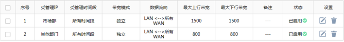
Click on “ Behavior control > Bandwidth limitation > Bandwidth allocation ”, Click on “ newly added ”, Set the following bandwidth control rules for the marketing department :

share Indicates the set uplink and downlink bandwidth shared by all computers in the address group .
Same method , Add bandwidth control rules for other departments . The list of rules after setting is as follows :
Conversion method
The downside Gigabit

The upside 300

demand 
Set up the success 
Question answer
Q1**、 What is the maximum bandwidth control limit ?**
Limiting bandwidth depends on two things : First, business needs , Different departments 、 The working requirements of the computer determine the demand for network bandwidth , This demand determines the percentage of the total bandwidth used ; Second, interface bandwidth , The total bandwidth of an enterprise determines the specific value allocated to each business host . For example, the total bandwidth of the company is 10M Optical fiber ,A department 10 Computers need to download 、 Upload 、 Send and receive mail , Then the maximum upstream and downstream limits for each host are 1500~2000Kbps.
Q2**、 After setting the bandwidth control, the effect is not obvious , What do I do ?**
The following three points need to be checked separately : Computer IP Whether the address is fixed 、 Controlled computer IP Whether the address belongs to the controlled address group 、 Control whether the bandwidth value setting is reasonable , Check and troubleshoot the above problems .
Q3**、 After setting the bandwidth control , Whether the controlled address group can continue to join IP?**
dEZDG-1655450234886)]
3. Set bandwidth control rules
Click on “ Behavior control > Bandwidth limitation > Bandwidth allocation ”, Click on “ newly added ”, Set the following bandwidth control rules for the marketing department :
[ Outside the chain picture transfer in …(img-RuUQeFBz-1655450234886)]
share Indicates the set uplink and downlink bandwidth shared by all computers in the address group .
Same method , Add bandwidth control rules for other departments . The list of rules after setting is as follows :
[ Outside the chain picture transfer in …(img-EguADw2a-1655450234887)]
Conversion method
The downside Gigabit
[ Outside the chain picture transfer in …(img-QpwaXjWC-1655450234887)]
The upside 300
[ Outside the chain picture transfer in …(img-gRgZRaxO-1655450234887)]
demand
[ Outside the chain picture transfer in …(img-rxvqweYh-1655450234887)]
Set up the success
[ Outside the chain picture transfer in …(img-qYSldiDB-1655450234887)]
Question answer
Q1**、 What is the maximum bandwidth control limit ?**
Limiting bandwidth depends on two things : First, business needs , Different departments 、 The working requirements of the computer determine the demand for network bandwidth , This demand determines the percentage of the total bandwidth used ; Second, interface bandwidth , The total bandwidth of an enterprise determines the specific value allocated to each business host . For example, the total bandwidth of the company is 10M Optical fiber ,A department 10 Computers need to download 、 Upload 、 Send and receive mail , Then the maximum upstream and downstream limits for each host are 1500~2000Kbps.
Q2**、 After setting the bandwidth control, the effect is not obvious , What do I do ?**
The following three points need to be checked separately : Computer IP Whether the address is fixed 、 Controlled computer IP Whether the address belongs to the controlled address group 、 Control whether the bandwidth value setting is reasonable , Check and troubleshoot the above problems .
Q3**、 After setting the bandwidth control , Whether the controlled address group can continue to join IP?**
Sure . Directly in “ Address management ” Edit the corresponding address group in , And fill in the IP Address segment , Finally, click “ determine ”.
边栏推荐
- 【本周六活动】.NET Day in China
- Anonymous Messenger: hidden communication of Trojan horse
- Qt: 判断字符串是否为数字格式
- H5 video conference, camera monitoring, web streaming and live broadcast integration scheme
- Canvas pipe animation JS special effect
- 今日睡眠质量记录76分
- Reliable remote code execution (1)
- 服乔布斯不服库克,苹果传奇设计团队解散内幕曝光
- [Flink source code practice (I)] add a rest API to Flink
- Rising bubble canvas breaking animation JS special effect
猜你喜欢

Svg+js drag slider round progress bar

Today's sleep quality record 76 points

@Requestbody annotation

软件测试 对前一日函数的基本路径测试

Cool interactive animation JS special effects implemented by p5.js

math_ Summation and derivation of proportional series & derivation of sum and difference of equal powers / difference between two nth power numbers/

Window function row in SQL Server_ number()rank()dense_ rank()

Use the process monitor tool to monitor process operations on registries and files

Differences among cookies, session, localstorage and sessionstorage

【本周六活动】.NET Day in China
随机推荐
math_等比数列求和推导&等幂和差推导/两个n次方数之差/
Group counting_ Structure and workflow of CPU
Tencent's open source project "Yinglong" has become a top-level project of Apache: the former long-term service wechat payment can hold a million billion level of data stream processing
How does easydss use go fastdfs distributed file servers to reduce service pressure?
What is recursion?
Déplacer Tencent sur le cloud a guéri leur anxiété technologique
Qt: 判断字符串是否为数字格式
Opencv optical flow prediction and remap remapping function usage
RPM installation percona5.7.34
TP-LINK 1208路由器教程(2)
Attribute observer didset and willset in swift of swiftui swift internal skill
I just did it! Visualization of character relationships in Douluo continent
Shell脚本(.sh文件)如何执行完毕之后不自动关闭、闪退?
Istio best practice: graceful termination
使用Process Monitor工具监测进程对注册表和文件的操作
Cool interactive animation JS special effects implemented by p5.js
如何开发短信通知和语音功能医院信息系统(HIS系统)
Today's sleep quality record 76 points
Network monitoring: active troubleshooting becomes simple
Canvas infinite scan JS special effect code