当前位置:网站首页>Gd32f3x0 official PWM drive has a small positive bandwidth (inaccurate timing)
Gd32f3x0 official PWM drive has a small positive bandwidth (inaccurate timing)
2022-06-26 05:11:00 【lljss2020】
1. Code
#include "gd32f3x0.h"
#include <stdio.h>
#include "gd32f350r_eval.h"

void gpio_config(void);
void timer_config(void);

/*! \brief configure the GPIO ports \param[in] none \param[out] none \retval none */
void gpio_config(void)
{

    /*Configure PB3 PB10 PB11(TIMER1 CH1 CH2 CH3) as alternate function*/
    gpio_mode_set(GPIOB, GPIO_MODE_AF, GPIO_PUPD_NONE, GPIO_PIN_3);
    gpio_output_options_set(GPIOB, GPIO_OTYPE_PP, GPIO_OSPEED_50MHZ,GPIO_PIN_3);

    gpio_mode_set(GPIOB, GPIO_MODE_AF, GPIO_PUPD_NONE, GPIO_PIN_10);
    gpio_output_options_set(GPIOB, GPIO_OTYPE_PP, GPIO_OSPEED_50MHZ,GPIO_PIN_10);

    gpio_mode_set(GPIOB, GPIO_MODE_AF, GPIO_PUPD_NONE, GPIO_PIN_11);
    gpio_output_options_set(GPIOB, GPIO_OTYPE_PP, GPIO_OSPEED_50MHZ,GPIO_PIN_11);

    gpio_af_set(GPIOB, GPIO_AF_2, GPIO_PIN_3);
    gpio_af_set(GPIOB, GPIO_AF_2, GPIO_PIN_10);
    gpio_af_set(GPIOB, GPIO_AF_2, GPIO_PIN_11);
}

/*! \brief configure the TIMER peripheral \param[in] none \param[out] none \retval none */
void timer_config(void)
{

    /* ----------------------------------------------------------------------- TIMER1 configuration: generate 3 PWM signals with 3 different duty cycles: TIMER1CLK is 1MHz TIMER1 channel1 duty cycle = (4000/ 16000)* 100 = 25% TIMER1 channel2 duty cycle = (8000/ 16000)* 100 = 50% TIMER1 channel3 duty cycle = (12000/ 16000)* 100 = 75% ----------------------------------------------------------------------- */
    timer_oc_parameter_struct timer_ocintpara;
    timer_parameter_struct timer_initpara;

    rcu_periph_clock_enable(RCU_TIMER1);

    timer_deinit(TIMER1);

    /* TIMER1 configuration */
#ifdef GD32F330
    timer_initpara.prescaler         = 83;
#endif /* GD32F330 */
#ifdef GD32F350
    timer_initpara.prescaler         = 107;
#endif /* GD32F350 */
    timer_initpara.alignedmode       = TIMER_COUNTER_EDGE;
    timer_initpara.counterdirection  = TIMER_COUNTER_UP;
    timer_initpara.period            = 15999;
    timer_initpara.clockdivision     = TIMER_CKDIV_DIV1;
    timer_initpara.repetitioncounter = 0;
    timer_init(TIMER1,&timer_initpara);

    /* CH1,CH2 and CH3 configuration in PWM mode */
    timer_ocintpara.outputstate  = TIMER_CCX_ENABLE;
    timer_ocintpara.outputnstate = TIMER_CCXN_DISABLE;
    timer_ocintpara.ocpolarity   = TIMER_OC_POLARITY_HIGH;
    timer_ocintpara.ocnpolarity  = TIMER_OCN_POLARITY_HIGH;
    timer_ocintpara.ocidlestate  = TIMER_OC_IDLE_STATE_LOW;
    timer_ocintpara.ocnidlestate = TIMER_OCN_IDLE_STATE_LOW;

    timer_channel_output_config(TIMER1,TIMER_CH_1,&timer_ocintpara);
    timer_channel_output_config(TIMER1,TIMER_CH_2,&timer_ocintpara);
    timer_channel_output_config(TIMER1,TIMER_CH_3,&timer_ocintpara);

    timer_channel_output_pulse_value_config(TIMER1,TIMER_CH_1,3999);
    timer_channel_output_mode_config(TIMER1,TIMER_CH_1,TIMER_OC_MODE_PWM0);
    timer_channel_output_shadow_config(TIMER1,TIMER_CH_1,TIMER_OC_SHADOW_DISABLE);

    timer_channel_output_pulse_value_config(TIMER1,TIMER_CH_2,7999);
    timer_channel_output_mode_config(TIMER1,TIMER_CH_2,TIMER_OC_MODE_PWM0);
    timer_channel_output_shadow_config(TIMER1,TIMER_CH_2,TIMER_OC_SHADOW_DISABLE);

    timer_channel_output_pulse_value_config(TIMER1,TIMER_CH_3,11999);
    timer_channel_output_mode_config(TIMER1,TIMER_CH_3,TIMER_OC_MODE_PWM0);
    timer_channel_output_shadow_config(TIMER1,TIMER_CH_3,TIMER_OC_SHADOW_DISABLE);

    /* auto-reload preload enable */
    timer_auto_reload_shadow_enable(TIMER1);
    /* auto-reload preload enable */
    timer_enable(TIMER1);
}

/*! \brief main function \param[in] none \param[out] none \retval none */
int main(void)
{

    rcu_periph_clock_enable(RCU_GPIOB);
    gpio_config();
    timer_config();

    while (1);
}
2. analysis
PWM frequency =84MHz/(83+1)/(15999+1)= 62.5Hz
timer_channel_output_pulse_value_config(TIMER1,TIMER_CH_1,3999);
Calculate it like this TIMER1 channel1 duty cycle = (3999/ 16000)* 100 = 24.99375%.
So the correct answer is
timer_channel_output_pulse_value_config(TIMER1,TIMER_CH_1,4000);
TIMER1 channel1 duty cycle = (4000/ 16000)* 100 = 25%
stay PWM It is not easy to find this problem when the frequency is very low , stay 10~100kHz when , The problem that the positive bandwidth is too small can be obviously found by oscilloscope .
边栏推荐
- thread priority
- Excellent learning ability is your only sustainable competitive advantage
- 百度API地图的标注不是居中显示,而是显示在左上角是怎么回事?已解决!
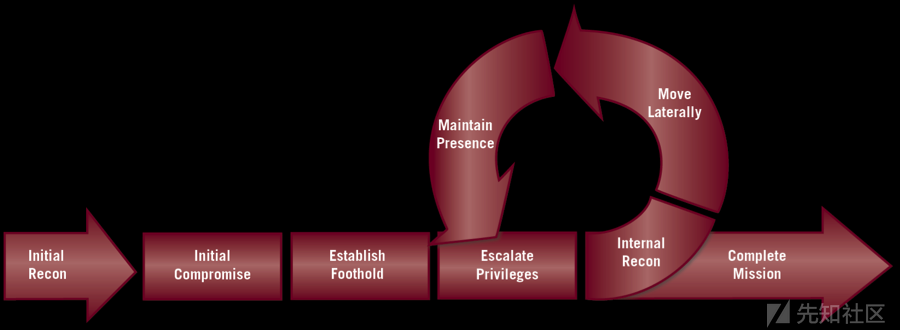
- 红队得分方法统计
- Using requests library and re library to crawl web pages
- [latex] error type summary (hold the change)
- ThreadPoolExecutor implements file uploading and batch inserting data
- Using Matplotlib to add an external image at the canvas level
- Create SSH key pair configuration steps
- Codeforces Round #800 (Div. 2)
猜你喜欢
【红队】要想加入红队,需要做好哪些准备?

How MySQL deletes all redundant duplicate data
Technical problems to be faced in mobile terminal im development
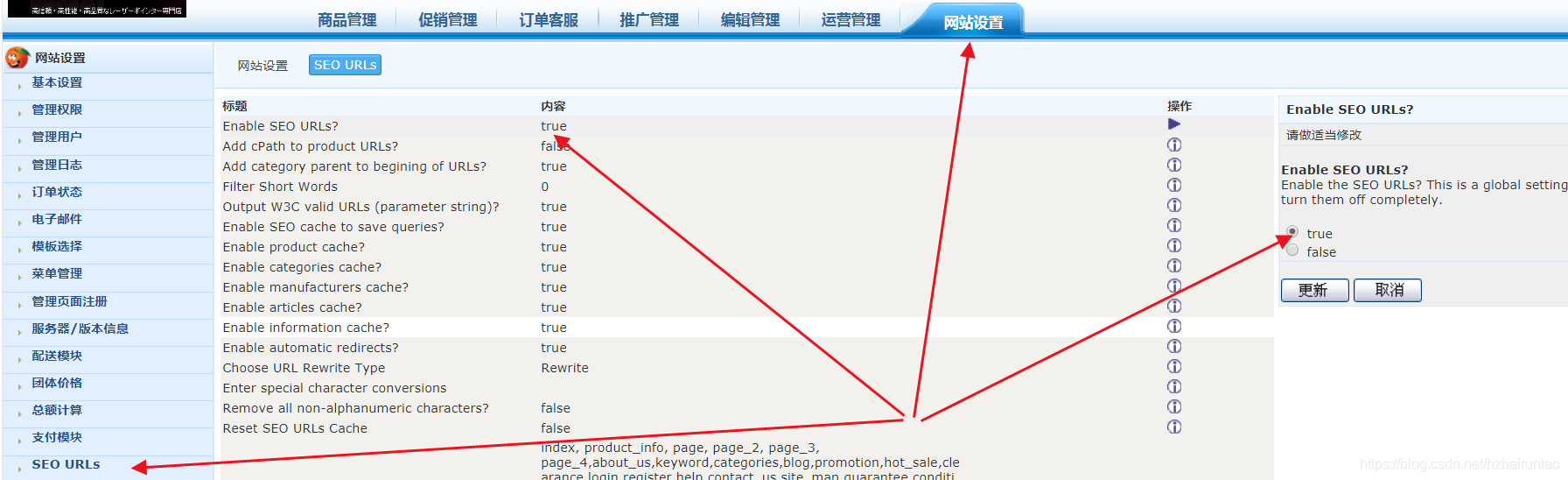
zencart新建的URL怎么重写伪静态

6.1 - 6.2 公鑰密碼學簡介

Decipher the AI black technology behind sports: figure skating action recognition, multi-mode video classification and wonderful clip editing

Zhongshanshan: engineers after being blasted will take off | ONEFLOW u

ModuleNotFoundError: No module named ‘numpy‘

Guanghetong and anti international bring 5g R16 powerful performance to the AI edge computing platform based on NVIDIA Jetson Xavier nx

Image translation /gan:unsupervised image-to-image translation with self attention networks

随机推荐
vscode config
Zuul implements dynamic routing
【上采样方式-OpenCV插值】
RESNET practice in tensorflow
Computer Vision Tools Chain
thread priority
Schematic diagram of UWB ultra high precision positioning system
torchvision_transform(图像增强)
UWB超高精度定位系统架构图
Astype conversion data type
ECCV 2020 double champion team, take you to conquer target detection on the 7th
Windows下安装Tp6.0框架,图文。Thinkphp6.0安装教程
pycharm 导包错误没有警告
Classic theory: detailed explanation of three handshakes and four waves of TCP protocol
Sentimentin tensorflow_ analysis_ cell
《财富自由之路》读书之一点体会
Computer Vision Tools Chain
tensorlow:cifar100_ train
A beginner's entry is enough: develop mobile IM from zero
Guanghetong and anti international bring 5g R16 powerful performance to the AI edge computing platform based on NVIDIA Jetson Xavier nx