当前位置:网站首页>Camera calibration (calibration purpose and principle)
Camera calibration (calibration purpose and principle)
2022-06-24 07:28:00 【No, libuxing】
1. The purpose of camera calibration :
(1) One is to correct the distortion of the picture caused by lens distortion , for example , Straight line in reality , When an image is taken, it will be convex or concave , This situation can be corrected after camera calibration ;
(2) The other is based on shooting Two dimensions of Image to reconstruct 3D scene , Because the calibration process is through a series of three-dimensional points and its corresponding two-dimensional image points for mathematical transformation , Find out the internal and external parameters of the camera .
Camera after calibration , Distance measurement can be carried out 、 3D scene reconstruction, etc .
2. Four coordinate systems
One of the purposes of camera calibration is to establish the corresponding relationship between the object from the three-dimensional world to the coordinate points on the imaging plane , So first we need to understand the following four coordinate systems :
World coordinate system : User defined coordinate system of three-dimensional world , It is introduced to describe the position of the object in the real world and the position of the camera .
Camera coordinate system : The coordinate system established on the camera , To describe the position of an object from the perspective of a camera , As a communication between the world coordinate system and the image / The middle part of the pixel coordinate system .
Image coordinate system : In order to describe the projection and transmission relationship between the camera coordinate system and the image coordinate system in the imaging process, this paper introduces , It is convenient to get the coordinates in the pixel coordinate system .
Pixel coordinate system : In order to describe the image point of the object after imaging on the digital image ( photo ) The coordinates of , It's the coordinate system that we actually read from the camera , The unit is ( Number of pixels ).
3. Transformation between coordinates
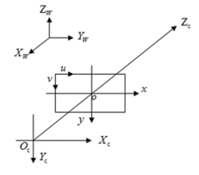
World coordinate system :Xw、Yw、Zw.
Camera coordinate system : Xc、Yc、Zc.
Image coordinate system :x、y.
Pixel coordinate system :u、v.
among , Camera coordinate system Z The axis coincides with the optical axis , It is perpendicular to the plane of the image coordinate system and passes through the origin of the image coordinate system , The distance between the camera coordinate system and the image coordinate system is the focal length f. Pixel coordinate system plane u-v And image coordinate system plane x-y coincidence , But the origin of the pixel coordinate system is located in the upper left corner of the figure .
3.1 World coordinate system to camera coordinate system
Hypothetical winding x Shaft rotation ( Anti-clockwise )
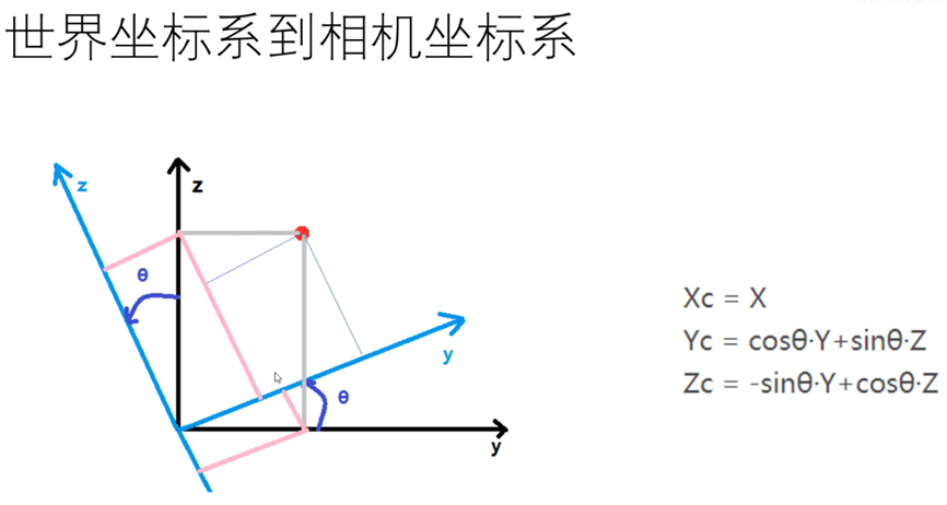

And so on , Rotate about other axes ( Clockwise )


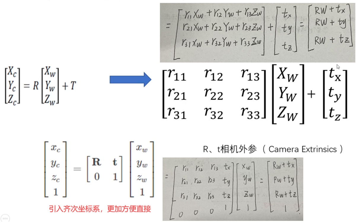
From the world coordinate system to the camera coordinate system 6 A degree of freedom , In addition to rotation, translation is also required
3.2 Camera coordinate system to image coordinate system

3.3 Image coordinate system to pixel coordinate system

The origin of the image coordinate system is in the center of the image , Company mm.
The origin of the pixel coordinate system is in the upper left corner of the image , Unit is pixel Pixel( individual ).
dx,dy: Is the intrinsic parameter of the sensor , Represents the number of millimeters per pixel .
u0,v0: Represents the offset of the origin of the image coordinate system from the pixel coordinate system , Unit is pixel .


3.4 The whole process of conversion from world coordinate system to pixel coordinate system 
thus , To reconstruct a 3D scene from a captured 2D image , Then it requires internal reference M1 And external reference M2.
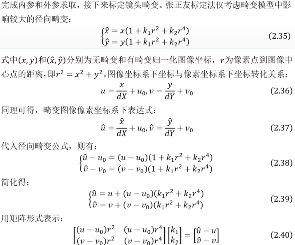
3.5 Zhang Zhengyou calibration method


 Homography (Homography) Transformation . It can be simply understood that it is used to describe the position mapping relationship between the object in the world coordinate system and the pixel coordinate system . The corresponding transformation matrix is called homography matrix .


![]()
How to get homography matrix according to calibration diagram ?
After a series of previous introductions , We should roughly understand how to calculate the homography matrix according to the printed chessboard calibration map and the photos taken H. Let's summarize the general process .
1. Print a checkerboard calibration drawing , Stick it on the surface of a flat object .
2. Take a group of pictures of checkerboards in different directions , It can be achieved by moving the camera , You can also move the calibration picture to achieve .
3. For each chessboard picture taken , Detect the feature points of all checkerboards in the picture ( Corner point , That is, the intersection of black and white chessboard in the figure below , Inside the magenta circle in the middle is a corner , Four diagonals ( Red yellow blue green ) Is the most special corner ). We define that the printed chessboard drawing is located in the world coordinate system Zw=0 On the plane of , The origin of the world coordinate system is located at the fixed corner of the chessboard drawing on the left ( For example, the yellow dot in the figure below ). The origin of the pixel coordinate system is located in the upper left corner of the picture on the right .

Because the chessboard calibration drawing all The spatial coordinates of the corners are known , The pixel coordinates of these corners corresponding to the corners in the captured calibration picture are also known , If we get this N>=4 Matching point pairs ( The more calculations, the more robust the results are ), It can be based on LM And so on Homography matrix in this view H. Of course, the calculation of homography matrix generally does not need to write its own function ,OpenCV There are ready-made functions that can call .
however , The above theory is just , In a real application scenario , The point pairs we calculate will contain noise . For example, the position deviation of a point is several pixels , Even the phenomenon of feature point pairing and mismatching , If only 4 A pair of points to calculate the homography matrix , There will be a big error . therefore , In order to make the calculation more accurate , Generally, it is much larger than 4 A pair of points to calculate the homography matrix . In addition, it is usually difficult to obtain the optimal solution by using the direct linear solution of the above equations , Therefore, other optimization methods are generally used in practical use , Such as singular value decomposition 、Levenberg-Marquarat(LM) Algorithm
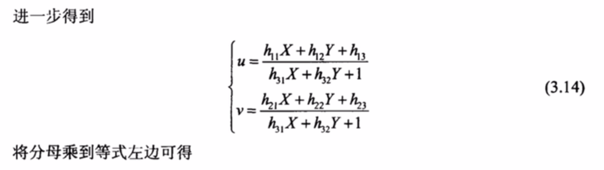
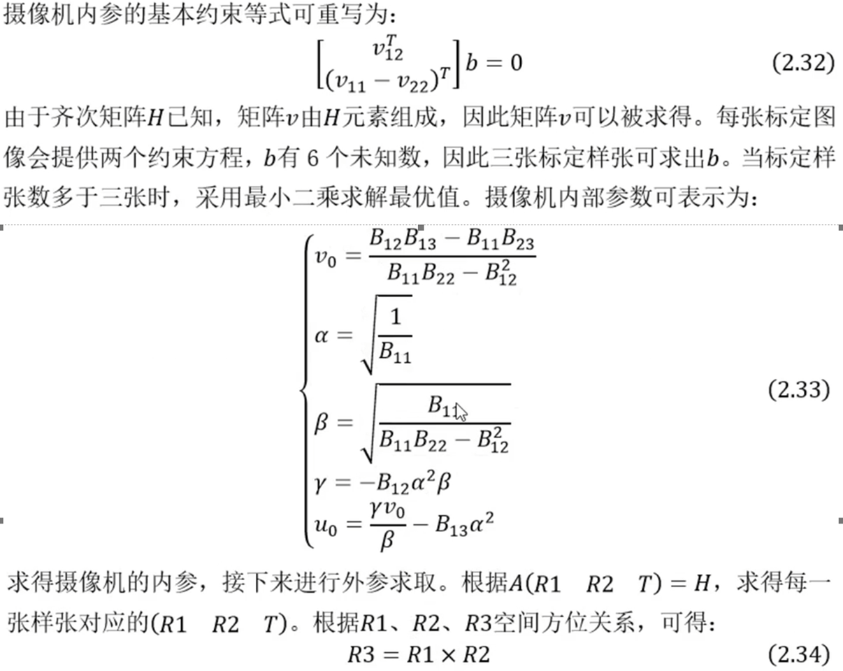
The homography matrix obtained by the above method H after , The following is through H Push back the internal and external parameters of the camera


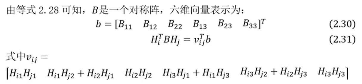
Pass above 2.28 And 2.29 have to :

It can be calculated by itself B It's a diagonal matrix , therefore B Only 6 An unknown number , So the vector b Set up 6 Just one parameter

Some of the pictures are from B Station video screenshot , Welcome to exchange and study .
It is strongly recommended to read this article : Detailed explanation of the mathematical principle of Zhang Zhengyou calibration method for camera calibration ( contain python Source code ) - You know
边栏推荐
- Mysql---三张表(student,课程,分数) 查询课程为数学的学生姓名,编号,成绩
- 利用微搭低代码实现级联选择
- 【帧率倍频】基于FPGA的视频帧率倍频系统verilog开发实现
- In JS, the regular expression verifies the hour and minute, and converts the input string to the corresponding hour and minute
- Bjdctf 2020 Bar _ Babystack
- 【图像融合】基于方向离散余弦变换和主成分分析的图像融合附matlab代码
- 如何删除/选择电脑上的输入法
- How can genetic testing help patients fight disease?
- 20个不容错过的ES6技巧
- Software performance test analysis and tuning practice path - JMeter's performance pressure test analysis and tuning of RPC Services - manuscript excerpts
猜你喜欢
![[GUET-CTF2019]zips](/img/79/22ff5d4a3cdc3fa9e0957ccc9bad4b.png)


随机推荐
The latest crawler tutorial in 2021: video demonstration of web crawling
[DDCTF2018](╯°□°)╯︵ ┻━┻
[WUSTCTF2020]爬
Huawei cloud database advanced learning
[WordPress website] 5 Set code highlight
Intranet learning notes (4)
How to connect the Bluetooth headset to the computer and how to connect the win10 computer to the Bluetooth headset
How to open the soft keyboard in the computer, and how to open the soft keyboard in win10
Kaseya of the United States was attacked by hackers, and 1500 downstream enterprises were damaged. How can small and medium-sized enterprises prevent extortion virus?
伦敦金的资金管理比其他都重要
jarvisoj_level2
[WUSTCTF2020]alison_ likes_ jojo
Win11 points how to divide disks? How to divide disks in win11 system?
Software performance test analysis and tuning practice path - JMeter's performance pressure test analysis and tuning of RPC Services - manuscript excerpts
MFC多线程 信号量CSemaphore 临界区与互斥 事件
[WordPress website] 6 Article content copy prevention
[image feature extraction] image feature extraction based on pulse coupled neural network (PCNN) including Matlab source code
When MFC uses the console, the project path cannot have spaces or Chinese, otherwise an error will be reported. Lnk1342 fails to save the backup copy of the binary file to be edited, etc
MySQL enable binlog
I failed to delete the database and run away