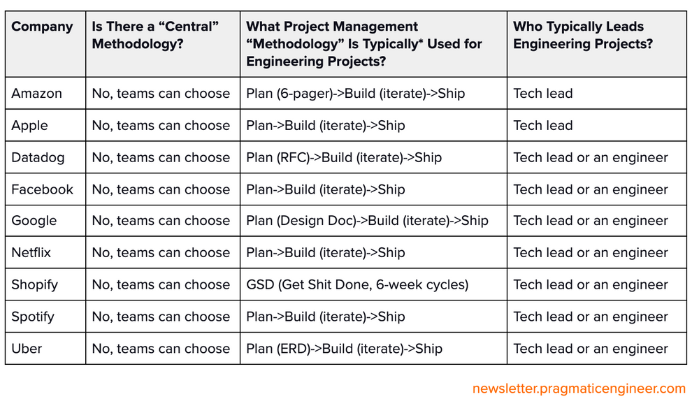
当前位置:网站首页>[Software Engineering] software engineering review outline of Shandong University
[Software Engineering] software engineering review outline of Shandong University
2022-06-27 07:25:00 【zj233333】
Software engineering review outline
This outline can be completely abridged , Test hit rate 100%, I took the exam first A4 paper :

1. Noun explanation question
1. Three elements of software engineering
- Method : It provides for software development “ How to do ” Technology , Such as project planning and estimation 、 Software system requirements analysis 、 data structure 、 The design of the overall structure of the system ;
- Tools : It provides automatic or semi-automatic software support environment for software engineering methods , Such as integrating software tools , Build what we call computer-aided software engineering (CASE) Software development support system .
CASEVarious software tools 、 The development machine is combined with an engineering database that stores the development process information to form a software engineering environment ; - The process : Integrate the methods and tools of software engineering to achieve reasonable 、 The purpose of developing computer software in time , It defines the : The order in which methods are used , Documents required to be delivered , Management required to ensure quality and adapt to changes , Milestones completed in each stage of software development .
2. Software engineering principles
- abstract : Extract the most basic characteristics and behaviors of things , Ignore non essential details , Adopt hierarchical abstraction , The top-down 、 Control the complexity of software development process by means of layer by layer refinement ;
- Information concealment : Design the module as “ black box ”, The implementation details are hidden inside the module , Do not allow users of the module to directly access . This is information encapsulation , The principle of separating use from implementation , The user can only access the data encapsulated in the module through the module interface ;
- modularization : A module is a logically independent component of a program , Is an independent programming unit , There should be a good interface definition . Such as C Function procedure in language program ,C++ Classes in language programs . Modularity helps to conceal and abstract information , Helps to represent complex systems ;
- deterministic : The expression of all concepts in the software development process shall be definite 、 Unambiguous 、 canonical . This helps people communicate without misunderstanding 、 missing , Ensure that the whole development work is coordinated ;
- Uniformity : The whole software system ( Including procedures 、 Documents and data ) A consistent concept should be used for each module of the 、 Symbols and terms . The internal interface of the program shall be consistent . Software and hardware 、 The interface of the operating system shall be consistent . The system specification shall be consistent with the system behavior . The axiomatic system used for formal specification should be consistent ;
- completeness : The software system does not lose any important components , The degree to which the required functions of the system can be fully realized . To ensure the completeness of the system , Strict technical review is required during software development and operation ;
- Verifiability : Developing large-scale software systems requires a top-down view of the system 、 Decompose layer by layer . The system decomposition shall follow the principle that the system is easy to check 、 test 、 The principle of review , To ensure the correctness of the system .
3. Software life cycle
4. Software development process
According to the progress of the project 、 Cost and quality constraints , An ordered collection of software development activities necessary to develop and maintain software that meets user needs .
5. Unified development process
It's not just a simple software process , It is a general process framework , It can be used in different types of application systems , It is component-based , The constructed software system is built by software components linked with each other through well-defined interfaces . And it uses UML Language to make all the blueprints of the system .
6. Software process model
Software process model is the framework of software development activities and their relationships in the whole process of software development , Used to guide software development . Common software process models are :
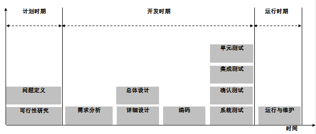
Waterfall model
The waterfall model describes the development phase as a waterfall transition from one phase to another , One stage must be completed before another begins , Each phase is accompanied by well-defined milestones and deliverables . In sequence :
- Demand analysis : Software requirements specifications ;
- The system design : Software system design documents ;
- Programming : Software function module algorithm and data description document ;
- code : Source program and comments ;
- Unit and integration testing : Unit and integration test reports ;
- The system test : System test report ;
- The acceptance test : Acceptance test report ;
- Operation and maintenance : Maintenance report ;
advantage : Intermediate products and interfaces are clearly defined , Developers can focus on completing each small phase , The testing and auditing process is complete , The overall quality of the system is high ;
shortcoming : inflexibility , Slow speed , It doesn't reflect the actual code development mode ; There is a high demand for developers , All requirements must be stated before the project starts ; The final product didn't appear until the end , Software customers can't get to the software prototype in the early stage .
Applicable occasions :① Stable product definition and demand analysis ;② Easy to understand but complex projects ;③ Quality demand is higher than cost demand and schedule demand ;④ The technical strength of the development team is weak or inexperienced .
Prototypes
When developers analyze requirements with users , Quickly build a prototype system that can reflect the needs of users at a low cost , Integrate the user's opinions to improve the prototype system , Then the user will evaluate , Repeat this process until the user is satisfied , Then start the formal design .
advantage : In line with the law of people's understanding of things , Shorten the distance between users and developers , Ensure that the designed software meets user requirements , Shorten the overall development cycle ;
shortcoming : It is difficult to simulate large-scale systems and batch processing systems , Documents are easily ignored , The project is difficult to plan and manage clearly .
Applicable occasions :① Software systems that do not define requirements in advance ;② Developers can't communicate well .
Incremental model
First, develop the main functions of the system , then , Over time , Add new secondary functions , Finally, a complete software product is developed .
advantage :① It helps to increase customers' confidence in the system ;② Reduce the risk of system failure ; Improve system reliability , Stability and maintainability ;
shortcoming :① Incremental granularity is difficult to choose ;② Each increment must depend on the previous increment , Coupling increases ;③ It is easy to degenerate into changing while doing , Losing the integrity of the software process .
Applicable occasions :① Upgrade existing products or develop new versions ;② Products with strict deadlines ;③ There are already prototype systems ;④ The overall level of developers is limited , You can learn and develop at the same time .
Spiral model
The basic method of spiral model is to “ Waterfall model ” Every ⼀ Three development phases ago , introduce ⼀ A very strict risk identification 、 Risk analysis and risk control . It decomposes software projects into ⼀ Small projects , Each small item is marked with ⼀ One or more major risks , Until all major risk factors are identified .
Four quadrant : Each iteration of the spiral model has four tasks , In turn, is : plan 、 The goal is / Alternatives 、 risk assessment 、 Development and testing ;
Four cycles : The spiral model has four iterations , In turn, is : Operational concepts 、 The software requirements 、 software design 、 Development and testing .
advantage :① Support dynamic changes in requirements , It has good expansibility ;② It is easy for users and developers to understand requirements , It can also be used as a basis for further development ;③ Emphasize risk analysis , The final security and stability of the software are greatly improved ;
shortcoming :① Developers should have rich knowledge of risk assessment ;② Long development cycle , More iterations , The project acceptance time may be delayed .
Agile development model
In order to alleviate the shortcomings of the traditional development model , The agile development model is proposed , It focuses on the evolution of users' needs , Use iterations 、 Step by step approach to software development , The overall goal is : As early as possible 、 Continuously deliver valuable software , Satisfy customers .
Agile Manifesto :
- Personal and interactive > Process and tools : Face to face communication rather than document communication ;
- Software production > Documentation : The measure of success is how well the software works ;
- Working with customers > Contracts and negotiations : Take the customer's demand as the leading core ;
- Reaction to change > Follow the plan : It is impossible to predict all the changes at the beginning .
Extreme programming (xp) :
Is a typical agile development method , contain 4 Three ideas :① communication : Continuous exchange of views between customers and developers ;② simplicity : Choose a simple implementation to meet customer needs ;③ Courage : Make early and regular commitments to delivery ;④ feedback : Various feedback activities should be carried out throughout the process .
Agile management practices :
- Daily Scrum Meeting : Before daily work , from
Scrum MasterLead team members to regularly communicate project progress and solutions on time ; - Visual management : Real time display of project status through physical entities , Let all team members get the current project progress information intuitively ;
- A user story : From the perspective of users , Describe user requirements in short sentences ;
- Pair programming : Use a keyboard , Two pairs of programmers , One responsible for typing in code , The other is to view each line of typed code in real time ;
- Test-driven development : Before writing any code , First write test cases that define the function of the code , The code is written through use cases ;
- Continuous integration : Team members often integrate their work , Usually everyone integrates at least once a day , Greatly shorten the feedback cycle ;
advantage :① Adopt a simple planning strategy , Long term planning and complex models are not required , Short development cycle ;② Adopt Iterative Incremental Development in the whole process 、 Feedback correction and repeated testing methods , It can adapt to the changing needs of users ;③ Focus on the ability to respond quickly to the market , High customer satisfaction in the early stage ;
shortcoming :① Pay attention to personnel communication , Ignore the importance of documents , If the project personnel flow is too large , It brings a lot of difficulties to maintenance ;② High requirements for the experience of coding personnel , If there are many novices in the project , Old employees are tired .
Scope of application :① Projects often change ;② High risk project implementation ;③ High level of developers , Can participate in decision-making ;④ There are excellent agile consultants .
7. Track project progress
Project progress : Project schedule is a description of the software development cycle of a specific project . Including the project phase 、 step 、 Decomposition of activities , A description of the interaction between discrete activities , And the preliminary estimate of the completion time of each activity and the completion time of the whole project .
Activities : Part of the project , Generally, it occupies a period of time in the project schedule ;
Milepost : Specific time nodes , It marks the end of the activity , It is usually accompanied by the submission of products ;
WBS:Work Breakdown Structure, term ⽬ Press ⼀ The principle of determination is decomposed , term ⽬ Break down into tasks , The task is broken down into ⼀ Item ⼯ do , And then ⼀ Item ⼯ Assign to each ⼈ Of ⽇ In regular activities , Until it can not be decomposed into ⽌, A tree represents ;
WBS decomposition method :① Analogy : Refer to similar project methods or templates ;② From the top down ;③ From the bottom up ;
Activity diagrams : Describe the dependencies between activities , The nodes in the figure are project milestones , Lines indicate activities ;
AOE The Internet : Directed graph
Gin , If you use vertices to represent events , Directed edges represent activities , The weight on the directed edge represents the duration of an activity , It's called a pictureGbyAOEThe Internet ;- critical path : The longest path from the source to the sink ;
- Key activities : Activities on critical path . Or activities that affect the shortest completion time of the whole project . That is, if it cannot be completed on time, the whole project will be affected .;
Project organization :
- Democratic programmers group : The members of the group are completely equal , Communicate with each other to make decisions , For smaller organizations ;
- Main programmer group : Each team member must communicate frequently with the lead programmer , Instead of communicating with other team members ;
- Modern programmer group : Combine the advantages of the Democratic programmer group and the master programmer group ,“ Master programmer ” By two people , The technical director is responsible for the technical activities of the group , The administrator is responsible for all non-technical management decisions .
8. Software scale evaluation method
① Code line analysis ;② Function point analysis ;③ Expert judgment techniques ;④ Standard regression technique ;⑤ Neural network technology ;⑥ Bayesian analysis techniques ;⑦ Analogy .
9. Software risk
The implementation of the software project is affected and lost 、 Even lead to failure 、 Possible events .
- Risk impact : Losses caused by risks ;
- Risk probability : Probability of occurrence of risk ;
- Risk exposure := Risk impact × Risk probability , Quantify the impact of the risk ;
- Three strategies to reduce risk :
- Avoid risks : By changing the performance or functional requirements of the software ;
- Transfer risk : Assign risks to other systems , Or buy insurance ;
- control risk : Assume in advance that the risk will occur , Accept and take measures to control in advance ;
- Risk leverage := ( Risk exposure before reduction - Reduced risk exposure ) / The cost of reducing risk , If the leverage is not high enough , Not enough to justify the action , Then other measures can be taken to reduce the risk .
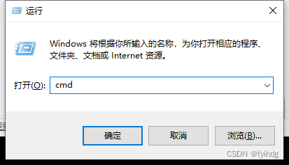
10. CASE
Computer aided software engineering , Used to support management system development 、 A large-scale comprehensive software development environment composed of various computer-aided software and tools , Tools as shown in the figure 、 Process modeling tools 、 Document authoring tools 、 A collection of integration testing tools .
11. demand
Demand is the expression of desired behavior , It is the software function that users need to solve a certain problem or achieve a certain goal ;
- functional requirement : Describe the functions or services expected to be provided by the system ;
- Non functional requirements : It refers to those requirements that are not directly related to the specific functions of the system , Such as concurrency , response time , reliability ;
- Domain needs : The application domain requirements of the system , If sensitive information is downloaded, it should be deleted in time ;
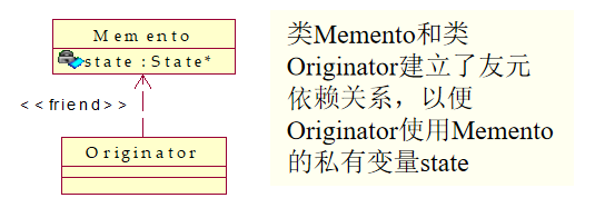
12. OCL( Object constraint language )
Object Constraint Language, Is a formal language , and ER Map or UML Close together , Used to represent invariants in class diagrams 、 precondition 、 Postcondition 、 Transfer conditions, etc , Help the class diagram to express more clearly .
13. Prototype requirements
Developers quickly build a prototype to ensure that it meets user needs , Start formal development after the requirements are determined ;
- Abandon prototypes : Write prototypes that are fast but do not consider quality , Can quickly grasp the core of the problem , Once a requirement is identified, discard it , Fast but poor iteratibility ;
- Evolutionary archetypes : Writing prototypes should not only capture the core of the problem , And iterating into the final product , Slow but highly iterative ;
- Rapid prototyping : These two methods are collectively referred to as rapid prototyping .
14. Design process model :

Software system design is an iterative process , The end result is software architecture documentation (SAD).
15. decompose
Decompose each module involved in the software from the top down , Help developers better grasp the software design process , Several popular decomposition schemes are :
- Function oriented decomposition : Break down functions or requirements into modules ;
- Feature oriented decomposition : It also decomposes functions or requirements into modules , However, detailed features have been developed for the module ;
- Data oriented decomposition : Decompose data into modules ;
- Process oriented decomposition : Decompose the system into a series of concurrent processes ;
- Event oriented decomposition : Decompose the events handled by the system into modules ;
- Object oriented decomposition : Decompose objects into modules ;
16. Modular
When each activity of the system is only realized by the corresponding software unit , And the input and output of each software unit have been clearly defined , Design can be said to be modular ;
17. Well defined
If the interface of a software unit can accurately specify the externally visible behavior of the unit , The software unit is said to be well-defined ;
18. View
After decomposing the software into components , Arrange them appropriately to show the interaction between various components and a representation of the overall architecture of the system ; The architecture view contains the following :
- Break down the view : for example UML Use case diagram , It is a hierarchical decomposition , A variety of models are used , Each module is programmable ;
- Dependent view : Shows the dependencies between software units , Help determine which units are independent , Which are coupled ;
- Generalized view : Shows whether a software unit is generalized by another unit , It is often used when designing Abstract units ;
- Execution view : Conventional Square box -> arrow View , It shows the structure of the system runtime , Each component is an execution entity ;
- Implementation view : Mapping between code units and source files , Help manage source code ;
- Deployment view : Running entities and IT Mapping between resources , Help analyze the underlying design of the system ;
- Assignment view : Each component is a task assigned to team members , Contribute to project management ;
19. Architecture style
Architecture style reflects the common structure and semantic characteristics of many systems in the domain , And guide how to effectively organize each module and subsystem into a complete system .
Classic architectural style :
The Conduit / filter : Input the data into the filter to get the output data , Data is piped from one filter to the next ;
- advantage :
- Each module is relatively independent , After the input and output are clearly defined , Facilitate modular development and testing ;
- Support some specific analysis , Such as throughput calculation and deadlock detection ;
- High concurrency , When the throughput of a module reaches the bottleneck , You can add the same build to share the pressure ;
- shortcoming :
- Weak interactive processing capability ;
- The specific implementation is more complex , For example, data stream synchronization and data encryption and decryption should be considered ;
- advantage :
hierarchy : The whole system is organized into a hierarchical structure , Each layer serves the upper layer , And as the next tier of customers .

advantage :
- The hierarchy style supports the level by level abstraction in the system design process ;
- The system based on hierarchy style has good scalability ;
- The hierarchical style supports software reuse ;
shortcoming :
- Not every system can be easily divided into hierarchical patterns ;
- It's hard to find a suitable 、 The right level of abstraction ;
C/S style :C/S The architecture has three main components : The client 、 Servers and dedicated networks ;
- advantage :① Rich interface , High operability ;② High safety ;③ Fast response ;
- shortcoming :① The scope of application is narrow ;② The user base is fixed ;③ Maintenance costs are high ;④ Special software shall be installed ;
B/S style :B/S The architecture has three main components : browser 、 Web The server 、 database server ;
- advantage :① It's easy to maintain and upgrade ;② Strong interaction ;③ Low requirements for client configuration ;
- shortcoming :① The cost of speed and security is enormous ;② Need to refresh the page ;③ Communication costs a lot ;
20. Design principles
Design principles are guidelines for decomposing system functions and behaviors into modules .
Six important design principles :
modularization : The principle of separating the irrelevant parts of the system , So that each part can study independently , Also known as separation of concerns , Each module has its own unique purpose , And relatively independent of other modules .
Two concepts are used to measure module independence : Coupling and cohesion ;
Coupling degree : There is a strong dependency between the two modules, which is called close coupling , There is less dependency between two modules, which is called loose coupling , No dependencies between modules are called uncoupled . The looser the coupling , The smaller the connection between modules , The more independent the module is .
Common coupling types :
- Indirect coupling : Both modules can work independently without the existence of another module , Lowest coupling ;
- Data coupling : The two modules exchange data with each other by transferring parameters , Called data coupling ;
- Tag coupling : The two modules transfer parameters and exchange complex data structure variables , Such as arrays 、 Class name ;
- Control coupling : The information transferred between the two modules is the control information , In loop and conditional judgment statements ;
- Public coupling : Each module accesses the same public data , Such as shared memory area , Read only public coupling is loose coupling , The common coupling between reading and writing is tight coupling ;
- Content coupling : The highest degree of coupling ,① One module directly accesses the internal data of another module ;② One module branches into another module ;③ Code sending overlaps between modules ;
Try to use data coupling , Use less control coupling , Limit the scope of public coupling , No content coupling at all .
Degree of cohesion : Cohesion is a measure of how closely each element in a module combines with each other , The more cohesive a module is , It indicates that the stronger the association between the elements within the module .
The cohesion is from low to high :
- To gather by chance : Just because of coincidence or convenience , Irrelevant functions 、 The process or data is in the same module , Is the worst kind of cohesion , The module is not easy to understand , Difficult to maintain , Not easy to reuse ;
- Logical cohesion : The parts of the module are only related by the logical structure of the code , But the actual function is not related ;
- Time converges : Each element must be executed at the same time ( For example, system initialization ), The advantage is that the implementation is simple , The disadvantage is that the module combines many unrelated tasks , Once the module fails , Difficult to locate the wrong location ;
- Process cohesion : There is a sequential relationship between elements , After calling the previous element , Immediately after the call , For example, lexical analysis must be carried out first , Can be parsed ;
- Communication cohesion : Each functional part of the module operates the same input , Or produce the same output , For example, both grammatical analysis and semantic analysis operate on the results of lexical analysis , Output intermediate code ;
- Order cohesion : The processing elements in the module are closely related to the same function , And these processes have to be performed in sequence , The output of the previous element is the input of the next element , For example, lexical analysis –> Syntax analysis –> Semantic analysis and intermediate code generation are integrated into one module ; Each part of the sequential cohesion module is closely related in function and execution sequence , Form an indivisible whole , Therefore, it is highly cohesive and easy to understand ;
- Functional cohesion : All processing elements in a module only work together to complete functions , Close ties , An integral , And there are no side effects , It's called functional cohesion . Functional cohesion is the highest degree of cohesion . In the design, the module shall reach the level of function cohesion as far as possible .
Interface : The interface defines the environment in which the module can work correctly , And formatted input and output , Hidden module implementation details ;
Information hiding : Hide module implementation related information from users who use the module , For example, the user only needs to know that the function can sort , It doesn't matter whether the bottom layer is bubble sort or quick sort ;
Incremental development : Think of each module as an incremental component , And analyze in batches according to priority 、 Design 、 Development 、 Test and deliver incremental components ;
abstract : Ignore details , Extract the commonness between modules , Or building an overall view , Or design interface classes ;
generality : When developing software , Try to make it a universal software , So that it can be reused in another system in the future ;
21. Three principles of object oriented
encapsulation 、 Inheritance and polymorphism ;
22. Object oriented design principles
Principle of single responsibility : A class has only one responsibility , This can increase the reusability of modules , The whole system is highly cohesive 、 Low coupling ;
Opening and closing principle : A software entity should be open to extension , Turn off for changes , That is, its behavior can be extended without changing its own code , When faced with new needs , Do not change existing code , Instead, it expands on it ;
- Abstraction is the key to the open close principle ;
Richter substitution principle : If a software uses a parent class , So it must apply to its subclass , The difference between a parent object and a child object is not obvious . That is said , In the software , Replace the parent class with its child class , The behavior of the program will not change , In short , Subtypes must be able to replace their parent types ;
- The reverse is not true , If a software entity uses a subclass , So it doesn't have to be able to use base classes ;
- Try to use base class types to define objects in your program , The subclass type is determined at run time , Replace the superclass object with a subclass object ;
- Subclasses can extend the methods of the parent class , But the method of the parent class cannot be modified , In essence, it is also a perfection of the opening and closing principle ;
Dependence Inversion Principle : High level modules should not rely on low level modules , They should all depend on abstraction . Abstractions should not depend on details , Details should depend on abstractions .
- To program for an interface , Don't program for implementation ;
- One of the common implementations is to use abstract classes in your code , Put the concrete class in the configuration file ;
- Coupling in an abstract way is the key to relying on the inversion principle ;
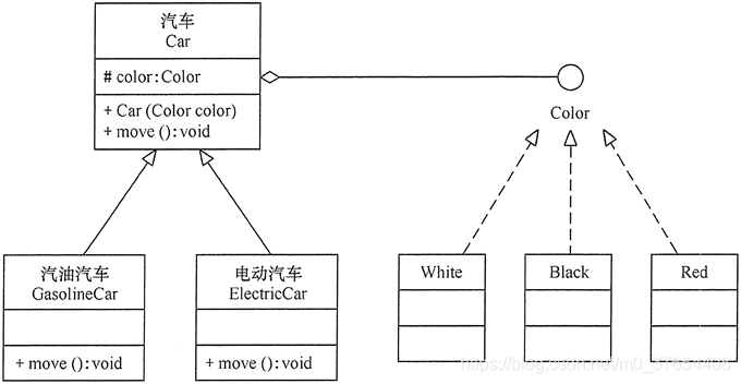
for example , The figure below 1 Dependency inversion principle not implemented , chart 2 Realized the principle of dependence reversal :


Synthetic multiplexing principle : Try to use object combinations , Instead of inheritance to achieve reuse ;
- When reusing, try to use Combine / polymerization Relationship , Use less inheritance ;
- Inheritance reuse is called white box reuse , Because the parent class is completely transparent to the child class , Combine / polymerization Multiplexing is black box multiplexing ;
for example , The figure below 1 Inheritance reuse , There are many redundant items , chart 2 It is aggregation reuse , Brief and easy to maintain :

Dimitar's law : Also known as the minimum knowledge principle , A software entity should interact with as few other entities as possible , such , When a module is modified , It will affect other modules as little as possible , Expansion will be relatively easy ;
- It can reduce the coupling between classes , So that they can be developed independently 、 Optimize 、 Use and modify ;
- The main purpose of Dimitri's law is to control the overload of information , For example, you should try to create loosely coupled classes , Minimize access to class member variables and functions , Try to reduce the number of references of class objects to other objects ;
for example , The figure below 1 The Dimitri principle is not used , chart 2 The Dimitri principle is used :


23. Object oriented design pattern
It's a set that's been used over and over again 、 Most people know that 、 Catalogued 、 Summary of code design experience , Design patterns realize the seven principles of object-oriented , Thus, code reuse is achieved 、 The purpose of increasing maintainability .
The singleton pattern : This pattern involves a single class , This class is responsible for creating its own objects , Also make sure that only a single object is created . This class provides a way to access its unique objects , You can directly access , There is no need to instantiate an object of this class .
- To avoid other programs creating too many objects of this class , It is forbidden to create other instances of this class first ;
- Hungry Chinese style : Object preload , Threads are safe , When the class is created, the object is generated , Calling the method to get the object instance is fast , The code is concise ;
- Slacker type : Object delay loading , Efficient , Instantiate objects only when they are used , Threads are unsafe if they are not designed properly , The code is relatively complex , The first time you load a class object, you don't react well .
Builder pattern : Separate the construction of a complex object from its representation , So that the same build process can create different representations , Such a design pattern is called the builder pattern . It is to decompose a complex object into many simple objects , And then build it step by step . It will be separated from the invariant , That is, the components of the product are the same , But each part can be chosen flexibly .
example :
With builders (Builder) Model description living room decoration .
analysis : Living room decoration is a complicated process , It includes the decoration of the wall 、 The choice of TV 、 Sofa purchase and layout, etc . The customer told the project manager about the decoration requirements , The project manager instructs the decorators to decorate step by step , Finally, finish the decoration and layout of the whole living room , So this example is more suitable for .
The living room here is a product , Include walls 、 TV and sofa, etc . The specific fitter is the specific builder , They are in charge of decoration and walls 、 The layout of TV and sofa . The project manager is the conductor , He is in charge of directing the fitters to carry out the fitment .
in addition , The living room class provides
show()Method , The decoration effect picture can be displayed . The client program uses the object generator classReadXMLReadXMLDecoration scheme data in the configuration file , Call the project manager for decoration . The class diagram is as shown in the figure :
The main advantages of the builder model are as follows :
- The client doesn't have to know the details of the product's internal composition , Decouple the product itself from the product creation process , It enables the same creation process to create different product objects ;
- Every concrete builder is relatively independent , It has nothing to do with other specific builders , So it's easy to replace specific builders or add new ones , Easy to expand , Comply with opening and closing principle ;
- You can control the product creation process more precisely ;
The disadvantages are as follows :
- The products created by the builder model generally have more in common , Its components are similar , If there is a big difference between products , Not suitable for builder mode , Therefore, its scope of use is limited ;
- If the internal changes of the product are complex , You may need to define many concrete builder classes to implement this change , It makes the system very large , It increases the understanding difficulty and operation cost of the system .
Observer mode : The observer (Observer) It refers to the existence of one to many dependencies between multiple objects , When the state of an object changes , All objects that depend on it are notified and automatically updated . This pattern is sometimes called Publishing - A subscription model 、 Model - View mode , It's an object behavior pattern .
Pattern motivation : Establish a dependency between objects , When an object changes, other objects are automatically notified , Other objects will respond accordingly . Here it is , The object of change is called the object of observation , And the informed object is called the observer , One observation target can correspond to multiple observers , And there's no connection between these observers , You can add and delete observers as needed , Make the system easier to expand , This is the motivation of the observer model .
example :
Use the observer pattern to design a program , Analyze the impact of appreciation or depreciation of RMB exchange rate on the cost of imported products of import companies, the income of export products of export companies and the profit margin of companies .
analysis : When “ RMB rate ” In appreciation , The cost of imported products of import companies is reduced and the profit margin is increased , The export company's export revenue and profit margin decrease ; When “ RMB rate ” When devalued , The cost of imported products of the import company increases and the profit margin decreases , Export company's export product income and profit margin increase .
The exchange rate here (Rate) Class is an abstract target class , It contains the preservation of the observer (Company) Of List And increase / How to delete an observer , And an abstract approach to exchange rate changes change(int number); And the exchange rate of RMB (RMBrate) Class is the specific target , It implements the change(int number) Method , That is, when the exchange rate of RMB changes, the exchange rate of RMB will be changed through related companies ; company (Company) Class is an abstract observer , It defines an abstract approach to exchange rate reactions response(int number); Import company (ImportCompany) Class and export company (ExportCompany) Class is a concrete Observer class , They implement the response(int number) Method , That is, when they receive the notice of exchange rate change, they will act as the corresponding response . The following figure shows its UML chart .
The advantages of the observer model :
- The specific target and the specific observer are loosely coupled , The introduction of the observer interface reduces the complexity of the system ;
- The observation mode satisfies “ open - Closed principle ”. The target interface depends only on the observer interface , The reusability and scalability of the system have been improved .
The disadvantages of the observer model :
- If an observer relates many instances , It takes a lot of time to notify all instances ;
- If there is a circular dependence between the observer and the observation target , Observing targets triggers a circular call between them , May cause system crash ;
- There is no corresponding mechanism for the observer model to let the observer know how the observed object changes , And just know that the observation target has changed .
Intermediary model : Define a mediation object to encapsulate the interaction between a series of objects , Make the coupling between the original objects loose , And they can change their interaction independently . The mediator model is also called mediation mode , It's a typical application of Dimitri's law .
example :
Write a with the mediator pattern “ Real estate exchange platform ” Program .
analysis : First , Define an intermediary company (Medium) Interface , It is an abstract mediator , It contains the customer registration method register(Customer member) And information forwarding methods relay(String from,String ad); Define a real estate agency (EstateMedium) company , It is a concrete mediator class , It contains... For storing customer information List object , And implements the abstract method in the intermediary company .
then , Define a customer (Customer) class , It is an abstract colleague class , It contains the object of the mediator , And sending messages send(String ad) Method and method of receiving information receive(String from,String ad) Method interface , Because this program is a form program , So this class inherits JPmme class , And realize the processing method of action events actionPerformed(ActionEvent e).
Last , Define seller (Seller) Class and buyer (Buyer) class , They are specific colleagues , It's the customer (Customer) Subclasses of classes , They implement the abstract methods in the parent class , Information exchange through intermediaries , Its structure UML The graph is as follows :
The advantages of the mediator model are :
- Each class performs its own duty , According to Dimitar's law ;
- Reduce the coupling between objects , Make objects easy to reuse independently ;
- Transform one to many relationships between objects into one to one relationships , Improve the flexibility of the system , Make the system easy to maintain and expand ;
The disadvantages of the mediator model are :
- The mediator pattern turns the direct interdependence of multiple objects into the dependency between mediators and multiple colleague classes . When there are more colleagues , The more bloated the intermediaries will be , Become complex and difficult to maintain .
24. Reuse
There are two types of reuse : Producer reuse and consumer reuse ;
- Producer reuse : The components being designed should be reused in future applications ;
- Consumer reuse : The components in use are those previously developed for other applications ;
25. Programming process
XP、 Pair programming 、 The fusion 、 Group collaboration ;
26. Software testing terminology
- error (error): It is often man-made ;
- fault (fault): Incorrect steps in the program , Process or data definition , This leads to unintentional 、 Unexpected behavior , Is usually
errorAs a result of ; - invalid (failure): A system or component cannot perform its required functions , Usually
faultAs a result of ;
27. Fault type
- Algorithm failure : Failure caused by some errors in source code writing or algorithm design ;
- Calculation fault and accuracy fault : Arithmetic expression error or calculation result does not reach the required precision ;
- Document failure : The documentation is inconsistent with what the program actually does ;
- Capability failure or boundary failure : When the system activity reaches the specified limit , System performance will become unacceptable ;
- Timing failure or coordination failure : The synchronous and mutually exclusive relationship between concurrent processes of the real-time system fails ;
- Throughput failure or performance failure : The system cannot perform at the speed required ;
- Standard and process failures : The code specification or style does not meet the requirements of the organization ;
28. Basic steps of software testing

- unit testing : Isolate each program component in the system from other components , Test each component individually for proper operation ;
- Integration testing : Ensure that the interfaces between components can operate normally , The components cooperate normally ;
- A functional test : It is an overall evaluation of the system , To determine whether the integrated system actually performs the functions described in the requirements specification , The result is a functioning system ;
- Performance testing : Test whether the system can be successfully implemented in the actual working environment of the customer , The result is a confirmed system ;
- The acceptance test : Exchange views with customers , To ensure that customer expectations are met , Complete the acceptance after confirmation with the customer ;
- Install the test : Install the accepted system in its actual working environment , Make sure it works correctly .
29. Unit test method
The static test ( The program does not execute ): It is generally to check the style and specification of the code .
- Static analyzer ( Automatic tools );
- Code review ( Artificial way );
Dynamic testing ( Program execution ): By selecting the appropriate test cases , Execution procedure .
Black box testing ( Testing capabilities ): Regardless of the internal structure and characteristics of the program , Design test cases only according to program functions or external characteristics of programs .
Classification of equivalence classes : The possible inputs are divided into several equivalent classes , Select a test case for each class ;
- Effective equivalence class : meaningful 、 Reasonable input data , Used to evaluate system functions ;
- Invalid equivalence class : meaningless 、 Unreasonable input data , Used to detect program exceptions ;
for example , Register for a website . requirement : The length of the user name is 812 A character composed of numbers and letters ,, The length of the password is 616 Digit number 、 The combination of letters . Please write a test case :

After the equivalence classes are determined, we can design test cases , Test cases need to cover all equivalence classes , That is, effective equivalence class and invalid equivalence class . Please see the table below for details :

Boundary value analysis : Test the input boundary value , for example , Yes 16-bit In terms of integers 32767 and -32768 Is the boundary ; The cursor is on the top left of the screen 、 Bottom right .
Wrong guess : When testing a program , People can infer from experience or intuition that there may be various errors in the program , So as to write a method to check these error test cases .
Cause and effect diagram : It is suitable for many input conditions , You can test the permutation and combination of all input conditions .“ because ” Is the input condition ,“ fruit ” Is the output .
White box testing ( Test structure ): Analyze the internal logical structure of the program , Pay attention to the selection of appropriate coverage criteria , Design test cases , Test the main path as much as possible .
White box method is also called logical covering method , Common logic coverage standards :
- Statement override : Every statement in a program can be executed at least once ;
- Determine coverage : Each decision in the program is at least
trueorfalseOnce each ; - Conditional coverage : Each conditional expression in the decision statement must be at least
trueorfalseOnce each , That satisfies the conditional coverage , It does not necessarily satisfy the decision coverage ; - determine / Conditional coverage : Both decision coverage and conditional coverage are satisfied ;
- Conditional combination covering : All possible combinations of conditions in the decision occur at least once , For example, a decision statement
iYesnConditions , Each condition hastrueandfalseOptions , At least2^nOnly use cases can cover statementsi.
30. Integration testing
Combine functional modules or program units for testing , Discover the defects of modules in the process of combination .
- Driver module : It is used to simulate the upper module of the module to be tested . The driver module receives the test data in the integration test , Transmit relevant data to the module to be tested , Start the module to be tested , And print out the corresponding results ;
- Pile module : It is used to simulate the module called during the working process of the module to be tested . The pile module is called by the module to be tested , They generally do little data processing , To facilitate the inspection of the interface between the module to be tested and the lower level module .
Classification of integration testing :
Non incremental integration strategy : After unit testing all modules , Connect the modules , Test the linked program as a whole .
Incremental integration strategy : The modules that have not been integrated and tested and the modules that have been integrated and tested ( Or subsystem ) Combined into packages , These modules are then integrated into a larger system , In the process of integration, test while connecting , To find problems in the connection process .
Incremental integration testing can be divided into three different methods :
Top down incremental testing : The sequence of module integration is to integrate the main control module first ( The main program ), Then the integration is carried out downward according to the control hierarchy . Press... Which is subordinate to the main control module
DFSorBFSMethods are integrated into the structure .The whole process consists of
3Step by step :- The main control module acts as a test driver ;
- The lower pile module is replaced by the real module again and again ;
- When each module is integrated , Must be unit tested . Repeat the first 2 Step , Until the whole system is tested .
Example : The following structures are tested with the top-down depth first strategy :


Analysis of advantages and disadvantages :
- advantage :① The main control and judgment points were verified earlier ;② You can first implement and verify a complete software function ;③ The function was confirmed earlier , Bring confidence ;④ Just one driver , Reduce the cost of drive development ;
- shortcoming :① The development of piles is large ;② The underlying validation was delayed ;
- Scope of application :① The product control structure is relatively clear and stable ;② The high-level interface changes little ;③ The underlying interface is undefined or may be modified frequently ;④ Product control components have high technical risks , It needs to be validated as soon as possible ;⑤ Hope to see the system function and behavior of the product as soon as possible .
Bottom up incremental testing : The most common integration strategy , Start with the underlying components that have the least dependencies , According to the structure of the dependency tree , Layer by layer integration , To test the stability of the system .
The whole process consists of
4Step by step :- The underlying leaf module starting from the module dependency tree ;
- Use the driver module for step 1 Test the selected modules ;
- Replace the drive module with the actual module , Assemble a larger module with its tested direct sub modules for testing ;
- Repeat the above behavior , Until the top module of the system is added to the tested system .

Analysis of advantages and disadvantages :
advantage :① Early verification of underlying component behavior ;② Work can initially be integrated in parallel , More efficient than top-down ; It reduces the workload of piles ;③ It can better lock the location of software fault .
shortcoming :① Driving development is a lot of work ;② The verification of the high level was delayed , Design mistakes can't be found in time .
Scope of application :① It is more stable to adapt to the underlying interface ;② High level interfaces change frequently ;③ The underlying components were completed earlier .
Sandwich incremental test : Divide the system into three layers , The middle layer is the target layer , Top down integration is adopted above the target layer , The bottom-up integration is adopted for the bottom-up integration .

The whole process consists of
4Step by step :- First, use top-down integration for the layer above the target layer ;
- Second, use bottom-up integration for the layer below the target layer ;
- third , Integrate the lower layer of the target layer with the target layer ;
- Last , Integrate the three layers .
Analysis of advantages and disadvantages :
- advantage : It combines the advantages of top-down and bottom-up strategies ;
- shortcoming : The middle layer test is not sufficient , It's hard to choose ;
- Scope of application : Suitable for most software development projects .
31. Software defect number estimation method
Seeding model :
Mills Model : Manual random placement error M A mistake , Test results m Error of personal worker placement ,n An inherent error in a program , Then the inherent error of the estimation system is :
N = n × M m N=\frac{n×M}{m} N=mn×MHyman Model : Two people test at the same time ,A Find out n A mistake ,B Find out m A mistake , Common mistakes are q individual , Then the inherent error of the estimation system is :
N = m × n q N=\frac{m×n}{q} N=qm×n
Static model : Estimate according to the size and complexity of the software .
Prediction model based on test coverage :

2. Comprehensive questions
2.1 draw AOE network
step :
- Calculate the earliest occurrence schedule of the event ,
earliest(j) = max{earliest(i) + w(i, j)}; - Calculate the latest occurrence schedule of the event ,
latest(i) = mim{latest(j) - w(i, j)};
example 1
As shown in the figure below AOE network ( The weight on the arc represents the duration of the activity , seek :
1) Plot the earliest occurrence time and the latest occurrence time of the event ;
2) Draw the earliest start time and the latest start time of the activity ;
3) What are the key activities , Give the critical path ;
4) How many days will it take to complete the project at least .


2.2 COCOMO Model
The basic workload calculation formula is as follows :
E = a × K L O C b × F E=a×KLOC^b×F E=a×KLOCb×F
① basic COCOMO:
| The way | a | b |
|---|---|---|
| Organic | 2.4 | 1.05 |
| Semi organic | 3.0 | 1.12 |
| The embedded | 3.6 | 1.2 |
E = a × K L O C b × 1 E=a×KLOC^b×1 E=a×KLOCb×1
One 33.3 KLOC Software development projects , It is of medium scale 、 Projects with semi existing models , Use basic COCOMO:a = 3.0,b = 1.12, be :
E = 3.0 × 33. 3 1.12 × 1 = 152 p m E= 3.0×33.3^{1.12}×1=152pm E=3.0×33.31.12×1=152pm
② secondary COCOMO:
| The way | a | b |
|---|---|---|
| Organic | 2.8 | 1.05 |
| Semi organic | 3.0 | 1.12 |
| The embedded | 3.2 | 1.2 |

F = ∏ i = 1 17 E M i F=\prod_{i=1}^{17}{EM_i} F=i=1∏17EMi
E = a × K L O C b × F E=a×KLOC^b×F E=a×KLOCb×F
One 33.3 KLOC Software development projects , It is of medium scale 、 Projects with semi existing models , Use medium COCOMO Model . a = 3.0,b=1.12, be :
F = 0.70 × 0.85 × . . . × 1.15 = 1.09 F=0.70×0.85×...×1.15=1.09 F=0.70×0.85×...×1.15=1.09
E = 3.0 × 33. 3 1.12 × 1.09 = 16 p m E=3.0×33.3^{1.12}×1.09=16pm E=3.0×33.31.12×1.09=16pm
③ senior COCOMO:

b = 0.91 + 0.01 ∑ i = 1 5 b i b=0.91+0.01\sum_{i=1}^{5}{b_i} b=0.91+0.01i=1∑5bi
F = ∏ i = 1 17 E M i F=\prod_{i=1}^{17}{EM_i} F=i=1∏17EMi
E = a × K L O C b × F E=a×KLOC^b×F E=a×KLOCb×F
a Is the correction constant , Usually the value is 2.94( Adjust according to the company's large amount of data ).
2.3 Decision tree analysis

2.4 E-R chart
stay ER The figure shows the following 4 Ingredients :

- Rectangle box : Represents an entity , Enter the entity name in the box ;
- Diamond frame : Represents the relationship between entities , Enter the contact name in the box ;
- Oval box : An attribute that represents an entity or relationship , Record the attribute name in the box , The primary attribute name should be underlined ;
- attachment : Between entity and attribute ; Between entities and connections ; The connection and attribute are connected by a straight line , And mark the type of connection on the line ;
- For one-on-one contact (1 ∶1): Write in the direction of the connection between the two entities 1;
- For one to many connections (1 ∶N) : Write on the side of one 1, More than one party to write N;
- For many to many relationships (N∶M) : Write in the direction of the connection between the two entities N,M.

Example 1: Use books 、 The author constructs two entities and their attributes and relationships E-R chart .
- The attributes of books : Book number 、 Title 、 Press. 、 Price ;
- The attributes of the author : ID number 、 full name 、 Age ;

Example 2: An enterprise group has several factories , Each factory produces a variety of products , And each product can be produced in multiple factories , Each factory produces products according to a fixed planned quantity , The planned quantity shall not be less than 300; Each factory employs more than one employee , And each employee can only work in one factory , The employees employed by the factory have the term of employment and salary . The attribute of the factory has the factory number 、 Factory name 、 Address , The attributes of a product have a product number 、 Product name 、 specifications , The attribute of an employee has an employee number 、 full name 、 Technical level .

2.5 UML chart
Class diagram to reflect the structure of the class ( attribute 、 operation ) And the relationship between classes , The structure of the software system is described , It is a static modeling method . It is divided into three parts from top to bottom , They are class names 、 Properties and operations .

Relationships in class diagrams :
Dependency relationship : Describes how a change in a class affects classes that depend on it ;
Dotted line + Arrow representation


Connections : Denote by a line segment with an arrow , Represents the connection between classes , One class uses the methods of another class ;


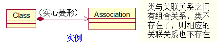
Aggregate relationship : Special relationships , Indicate an aggregation ( whole ) And the relationship between components . for example , Several students gathered into a class , Students will not be unable to exist because of the dissolution of the class , The classroom needs to know both class and student information , The life cycle of the two is independent ;


synthetic relation : More semantic aggregation , Parts and whole have the same life cycle . for example , Students are made up of organs , The life cycle of the organ is strictly encapsulated in the students , You only need to know the students' information ;

Generalization relation : It is generally called inheritance relationship in object-oriented , Exists in parent and child classes 、 Between parent interface and child interface ;


Realization relationship : Corresponding to the relationship between classes and interfaces ;
Dotted line + A hollow triangle represents


2.6 Petri network
Example 1


Example 2
There is an industrial production line , There are two things to do , They are changes t1 and t2 Express , Changes t1 Will enter the production line , Partially Prepared Products s1s2 With two parts s3 Fixed together , After that, the middleware is formed s4. Then the first 2 Changes t2 take s4 and s5 use 3 Parts s3 Fixed together to form a middleware s6. complete t1 and t2 All need tools s7.
Suppose you are limited by space ,s2、s5 Not more than 100 Pieces of , s4 Not more than 5 Pieces of ,s3 Not more than 1000 Pieces of .
Its Petri The net results are as follows :

2.7 Data flow diagram

Top level map : The middle ellipse is the system to be developed , The surrounding rectangle represents the external entity person or organization ;
Middle level chart : take “ Top level data flow diagram ” Refinement , The external entity does not change ;
The bottom map : For each process node , Break it up , Draw a more detailed picture of the data flow ;
** Example :** Book reservation system : Bookstores issue orders to customers , The customer submits the filled order to the system for processing , The system first checks the order according to the book catalog and processes the qualified order , In the process of processing, the orders are divided into priority orders and normal orders according to the situation of customers and the number of orders , Handle priority orders at any time , Process regular orders on a regular basis . At last, the system will summarize according to the processed orders , And send it to the publishing house according to the requirements of the publishing house .
First step , Draw the associated data flow diagram :

The second step , Layer by layer decomposition processing , Draw the lower layer DFD:
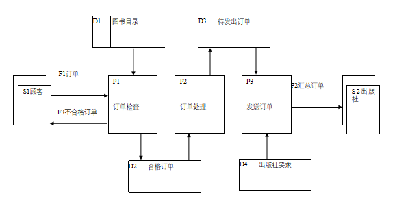
The third step , Refine the intermediate process , Draw the bottom layer DFD:

2.8 UML Use case diagram
Similar to the top-level data flow diagram , Describes the upper level interaction between the system and users .
Relation and explanation in use case diagram

Example 1:
participants : The manager , Safety Supervisor , Security staff
Use cases : Manage personnel , Approve the budget , Approve the safety certificate , Monitor surroundings

Example 2:
A short trip, but the car doesn't have enough oil to cover the whole journey . So the action of refuelling the car in every scene of the trip ( Flow of events ) Will appear in , You can't finish your trip without refueling . Eating can be decided by the driver , Not eating will not affect the completion of the trip .

2.9 Fault tree analysis
Fault tree is an inverted tree logic causality diagram established to study the fault of a certain function of the system .

The edge of the cut set tree is the cut set of the fault tree , Represents the minimum set of events required to cause a tree top failure .
If the cut set of the fault tree and the probability of sending the bottom event are known , Then the probability of sending the top event is the sum of the occurrence probabilities of each cut set element .
边栏推荐
猜你喜欢

vs怎么配置OpenCV?2022vs配置OpenCV详解(多图)

用XGBoost迭代读取数据集

Idea one click log generation

2022 le fichier CISP - Pte (i) contient:
How to download opencv? How to configure opencv after downloading?

What is the difference between volatile and synchronized?

正斜杠反斜杠的由来
Goodbye, agile Scrum

yarn create vite 报错 ‘D:\Program‘ 不是内部或外部命令,也不是可运行的程序 或批处理文件
Winow10 installation nexus nexus-3.20.1-01
随机推荐
MySQL
Apifox learning
(已解决) MINet 进行测试时报错如下 raise NotImplementedError
VNC Viewer方式的远程连接树莓派
专业四第二周自测
Hutool symmetric encryption
Visual Studio VS 快捷键使用大全
R 语言并行计算 spearman 相关系数,加快共现网络(co- occurrence network)构建速度
如何优雅的写 Controller 层代码?
延时队列`DelayQueue`
Easyexcel: read Excel data into the list set
HTAP Quick Start Guide
SQL考勤查询间隔一小时
View functions in tidb
[openairinterface5g] rrcsetupcomplete for RRC NR resolution
From 5 seconds to 1 second, the system flies
HTAP in depth exploration Guide
Classical cryptosystem -- substitution and replacement
使用 Blackbox Exporter 测试网络连通性
volatile 和 synchronized 到底啥区别?