1、Profibus DP networking
What is? Profibus The Internet
Profibus Full name Process Field Bus It's a kind of internationalization , Open fieldbus standards that do not depend on equipment manufacturers .
Profibus Network features
1) Communication medium
chart 1-1
Pictured 1-1 Shown in Profibus The communication media that can be used under the communication mode include shielded twisted pair and optical fiber , Short distance communication, of course (1 km ) We usually use shielded twisted pair , When the communication distance is long (1 Km above ) Shielded twisted pair cable can no longer meet the communication requirements. Optical fiber is our only choice .
2) transmission distance
chart 1-2
From the figure 1-2 It is shown that the length of the communication distance is closely related to the communication rate due to the physical properties of the copper conductor when using the shielded twisted pair , The communication distance is inversely proportional to the communication rate , Here we need to pay attention to the figure 1-2 The relationship between communication rate and length listed in is only a theoretical value , We can only take it as a reference when doing the project , Due to the complexity of the site conditions and the quality of the wires used, the relationship between the actual communication distance and the communication rate needs to be set in combination with the actual situation of the site .
When using optical fiber as communication medium, we can use higher communication rate in longer communication distance due to the physical characteristics of light propagation .
3) Number of nodes
The number of nodes is the number of nodes Profibus How many supports can there be in the network Profibus Communication protocol hardware , So in Profibus Up to... Can be supported in the network 127 Network nodes
4) Network topology
chart 1-3
Generally, the whole network shall be established as shown in the figure 1-3 Bus type status shown , This is the most effective and reliable network structure in practical application .
2 long-range I/O Introduce We have introduced what is Profibus The Internet , Then at the beginning of master station and remote station I/O Before explaining the hardware configuration, I think it is very necessary to introduce the master station and the remote I/O The role of , And all kinds of hardware used to form such a network .
long-range I/O The role of
Through the learning of single rack expansion and multi rack expansion , You should be aware that there are two fatal drawbacks to using interface modules to expand the rack .
1) Limit on the number of signal modules , Even for multi rack expansion, we can only use 32 A signal module .
2) Second, the limitation of communication distance , For single rack expansion mode, the distance between racks can only be 1 rice , And multi rack expansion , The distance between racks is the most 10 rice .
So because of these two fatal shortcomings , When the field control range is large and the control points are scattered, it is very impractical to complete such distributed system integration through the interface module . Then we need to use Profibus Network to complete our task .
long-range I/O Hardware details
chart 2-1
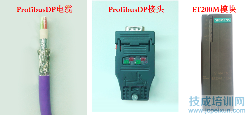
chart 2-1 Is to complete remote I/O The main hardware used for networking ( Of course, remove CPU outside ), Let's introduce the three hardware one by one .
1) Shielded twisted pair
chart 2-2
chart 2-2 Shown is the standard Siemens Profibus The structure of the cable is communication cable from inside to outside 、 Cable protective layer 、 silver paper 、 Shielding net and cable sheath , It should be noted that the tin foil and the shielding net jointly undertake the important task of shielding electromagnetic interference .
2) Profibus DP Joint
chart 2-3
chart 2-4
chart 2-5
Pass diagram 2-3、 chart 2-4、 chart 2-5 Shown , I clearly show you ProfibusDP External and internal structure of the joint , Pay attention to the terminal resistance during networking , Only the two ends of the network Profibus DP The connector needs to be switched to on, Other sites must dial off.
Now that I have introduced to you in detail ProfibusDP Cable and Profibus DP Joint , Next, I will introduce how to connect the two components according to the specifications and standards .
chart 2-6
In the figure 2-6 How to show you how to make ProfibusDP Several elements of a joint
A. The copper core twisted pair must be measured to an appropriate length , Then cut .
B. The shielding net and tin foil must be crimped Profibus DP Metal area of joint .
C. The purple cable sheath should be cut just below Profibus DP Joint metal area .
3) ET200M modular
chart 2-7
chart 2-8
chart 2-9
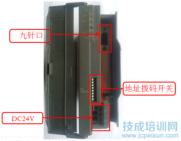
chart 2-7、 chart 2-8、 chart 2-9 Namely ET200M External view of the module 、 Internal view and station address dial switch. It should be noted here that the settable range of station address is 1 To 127.
3、 Hardware configuration 1) Create a new project and insert 300 Site
chart 3-1
2) Set up the rack to plug in the power supply CPU Parallel configuration Profibus DP The Internet
chart 3-2
3) configuration ET200M modular
chart 3-3
4) Configure the signal module
chart 3-4
chart 3-5


