当前位置:网站首页>[STM32 learning] (22) STM32 realizes 360 degree rotary encoder
[STM32 learning] (22) STM32 realizes 360 degree rotary encoder
2022-07-24 09:50:00 【Use small materials】
360 degree The object of rotary encoder is as follows :

KY-040 Rotary encoder module
Working voltage :5V
Number of pulses per cycle :20
The rotary encoder can count the number of output pulses in the process of positive and negative rotation by rotation , Rotation counting is not like potentiometer , This rotation count is unlimited . Cooperate with the keys on the rotary encoder , It can be reset to the initial state , From 0 Start counting .
working principle : Incremental encoder is a kind of rotary sensor that converts rotary displacement into a series of digital pulse signals . These pulses are used to control the angular displacement . stay Eltra The conversion of angular displacement in the encoder adopts the photoelectric scanning principle . The reading system consists of a radial dividing plate composed of alternating light transmission windows and light tight windows ( Code disk ) Based on the rotation of , At the same time, it is vertically illuminated by an infrared light source , Light projects the image of the code disk onto the surface of the receiver . The receiver is covered with a diffraction grating , It has the same window width as the code disk . The work of the receiver is to feel the changes caused by the rotation of the disc , Then convert the light change into the corresponding electrical change . Then raise the low-level signal to a higher level , There is no square pulse without any interference , This must be handled by electronic circuits . The reading system usually adopts differential mode , That is, the two waveforms are the same, but the phase difference is 180° Compare different signals , In order to improve the quality and stability of the output signal . The reading is based on the difference between the two signals , Thus, the interference is eliminated .

The incremental encoder gives two-phase square wave , Their phase difference 90°, Often referred to as A Channels and B passageway . One of the channels gives information related to speed , meanwhile , Compare the signals of two channels in sequence , Get information about the direction of rotation . There is also a special signal called Z Or zero channel , This channel gives the absolute zero position of the encoder , This signal is a square wave and A The center lines of the channel square waves coincide .
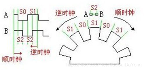
Now realize the detection of this incremental encoder Positive rotation still reverse
Here we use read IO To read data , To determine whether it is a forward turn or a reverse turn .
Single chip model :STM32L052K8*
connection :CLK Pick up PA0
DT Pick up PA1
SW Pick up PA2
int main(void)
{
  /* USER CODE BEGIN 1 */
	unsigned char dt;
	unsigned char clk,key;
  /* USER CODE END 1 */

  /* MCU Configuration--------------------------------------------------------*/

  /* Reset of all peripherals, Initializes the Flash interface and the Systick. */
  HAL_Init();

  /* USER CODE BEGIN Init */

  /* USER CODE END Init */

  /* Configure the system clock */
  SystemClock_Config();

  /* USER CODE BEGIN SysInit */

  /* USER CODE END SysInit */

  /* Initialize all configured peripherals */
  MX_GPIO_Init();
  MX_USART1_UART_Init();
  /* USER CODE BEGIN 2 */
	printf("\n\r****wantin****\n\r");
  /* USER CODE END 2 */

  /* Infinite loop */
  /* USER CODE BEGIN WHILE */
  while (1)
  {
    /* USER CODE END WHILE */

    /* USER CODE BEGIN 3 */
	  printf("\n\**************\n\r");
	  clk = HAL_GPIO_ReadPin(DT_GPIO_Port,DT_Pin);
	  dt = HAL_GPIO_ReadPin(DT_GPIO_Port,DT_Pin);
	  key = HAL_GPIO_ReadPin(SW_GPIO_Port,SW_Pin);
	  if(1 == clk)
	  {
		  printf("\n\clk == 1\n\r");
	  }
	  else
	  {
		  printf("\n\clk == 0\n\r");
	  }
	  if(1 == dt)
	  {
		  printf("\n\dt == 1\n\r");
	  }
	  else
	  {
		  printf("\n\dt == 0\n\r");
	  }
	  if(1 == key)
	  {
		  printf("\n\key == 1\n\r");
	  }
	  else
	  {
		  printf("\n\key == 0\n\r");
	  }
	  HAL_Delay(1000);
  }
  /* USER CODE END 3 */
}
In terms of implementation effect , Not ideal :

Whether you turn forward or backward ,CLK and DT The level of these two pins , All are successful 0、1 alternate , And the two levels are the same , It is impossible to distinguish between forward rotation and reverse rotation .
And then , Plug it in , Use an oscilloscope to test the waveform generated by these two pins . The effect is as follows :
Acquisition interrupted 0 mouth , And then clk The signal
Waveforms of forward rotation : The yellow line is clk, The blue line is dt
Falling edge trigger , Collected level All for Low level clk = 0 dt = 0;
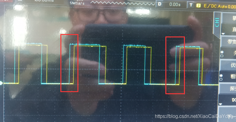
Inverted waveform : The yellow line is clk, The blue line is dt
Falling edge trigger , Collected level clk = 0 dt = 1;

It can be seen from the waveform that , There is waveform difference between positive and negative , How to realize forward and reverse detection , Interrupt can be used to realize .
Adopt the falling edge trigger method to collect the changes of waveform .
int main(void)
{
  /* USER CODE BEGIN 1 */
	unsigned char dt;
	unsigned char clk,key;
  /* USER CODE END 1 */

  /* MCU Configuration--------------------------------------------------------*/

  /* Reset of all peripherals, Initializes the Flash interface and the Systick. */
  HAL_Init();

  /* USER CODE BEGIN Init */

  /* USER CODE END Init */

  /* Configure the system clock */
  SystemClock_Config();

  /* USER CODE BEGIN SysInit */

  /* USER CODE END SysInit */

  /* Initialize all configured peripherals */
  MX_GPIO_Init();
  MX_USART1_UART_Init();
  /* USER CODE BEGIN 2 */
	printf("\n\r****wantin****\n\r");
  /* USER CODE END 2 */

  /* Infinite loop */
  /* USER CODE BEGIN WHILE */
  while (1)
  {
    /* USER CODE END WHILE */

    /* USER CODE BEGIN 3 */
	  printf("\n\**************\n\r");
	  if(10 == spped_counter)
	  {
		  printf("\n\*** Positive rotation ***\n\r");
	  }
	  else
	  {
		  printf("\n\*** reverse ***\n\r");
	  }
//	  clk = HAL_GPIO_ReadPin(DT_GPIO_Port,DT_Pin);
//	  dt = HAL_GPIO_ReadPin(DT_GPIO_Port,DT_Pin);
//	  key = HAL_GPIO_ReadPin(SW_GPIO_Port,SW_Pin);
//	  if(1 == clk)
//	  {
//		  printf("\n\clk == 1\n\r");
//	  }
//	  else
//	  {
//		  printf("\n\clk == 0\n\r");
//	  }
//	  if(1 == dt)
//	  {
//		  printf("\n\dt == 1\n\r");
//	  }
//	  else
//	  {
//		  printf("\n\dt == 0\n\r");
//	  }
//	  if(1 == key)
//	  {
//		  printf("\n\key == 1\n\r");
//	  }
//	  else
//	  {
//		  printf("\n\key == 0\n\r");
//	  }
	  HAL_Delay(1000);
  }
  /* USER CODE END 3 */
}
void HAL_GPIO_EXTI_Callback(uint16_t GPIO_Pin) // External interrupt Callback function
{
if(GPIO_Pin == CLK_Pin) // If any change is detected, come in and deal with it
{
if(HAL_GPIO_ReadPin(CLK_GPIO_Port,CLK_Pin) == HAL_GPIO_ReadPin(DT_GPIO_Port,DT_Pin)) //clk pb0 == dt pb1
spped_counter=10; // Express Positive rotation
else
spped_counter=100; // Express reverse
}
}
The effect is as follows :

边栏推荐
- S2b2b system standardizes the ordering and purchasing process and upgrades the supply chain system of household building materials industry
- Synchronized scope "concurrent programming"
- 07 Jason module
- PHP Basics - PHP super global variables
- Getting started with identityserver4
- Boundless dialogue | participate in the live broadcast on July 25 and win the prize
- Get the historical quotation data of all stocks
- PHP caching system - PHP uses Memcache
- PHP debugging tool - socketlog installation and usage
- 【机器人学习】机构运动学分析与matlab仿真(三维模型+word报告+matlab程序)
猜你喜欢

The most complete solution for distributed transactions

Getting started with web security - open source firewall pfsense installation configuration

Li Kou 300 longest increasing subsequence dynamic programming

【机器人学习】机构运动学分析与matlab仿真(三维模型+word报告+matlab程序)

note: expected ‘void * (***)(void ***)’ but argument is of type ‘void (*)(void *)’

07 Jason module

Racecar multi-point navigation experiment based on ROS communication mechanism
![Cyclicbarrier and countdownlatch [concurrent programming]](/img/38/3305a0cdb6de40e1370cc93c8e5014.png)
Cyclicbarrier and countdownlatch [concurrent programming]

Write a simple memo using localstorage

Will your NFT disappear? Dfinity provides the best solution for NFT storage
随机推荐
Vim: use tags file to extend the automatic code completion function of YCM for the third-party library of C language
Financial digital transformation
[don't bother with reinforcement learning] video notes (I) 2. Summary of reinforcement learning methods
PHP debugging tool - how to install and use firephp
Arduino drive lcd1602a
Raspberry Pie: [failed] failed to start /etc/rc local Compatibility.
Getting started with web security - open source firewall pfsense installation configuration
Jenkins post build script does not execute
Huawei wireless device security policy configuration command
What are the 6% annualized products?
Spark Learning: implement compact table command
Spark Learning: using RDD API to implement inverted index
[don't bother with intensive learning] video notes (III) 1. What is SARS?
获取所有股票历史行情数据
Android Version Description security privacy 13
[don't bother with reinforcement learning] video notes (I) 3. Why use reinforcement learning?
Add SSH key to bitbucket
Arduino drive Lora module master node
Implementation principle of acid in MySQL
ThreeJs