当前位置:网站首页>Hardware knowledge 1 -- Schematic diagram and interface type (based on Baiwen hardware operation Daquan video tutorial)
Hardware knowledge 1 -- Schematic diagram and interface type (based on Baiwen hardware operation Daquan video tutorial)
2022-07-23 12:15:00 【Mountains】
One 、 Schematic diagram
Schematic diagram , It is a diagram showing the connection principle between devices on the circuit board . Through the analysis of the schematic diagram , You can understand the input and output of a module , See the specific parameters of each electronic component and the connection relationship between each component . Through the schematic diagram, users can quickly get familiar with some structures and relationships of the system .
1.1 Common devices
On the circuit board , Because of the limited space , It is impossible to write out the names of each component , So all kinds of devices are abstracted into symbols to represent . Use a specific number to indicate the type of components . For example, use R Represents resistance , A number added to the back indicates a specific resistance , Such as R1、R2、R3 Each represents three resistors .

Through the above component number , The user can know the specific components on the circuit board .
1.2 Representation of device connection
1、 use attachment Indicates that there is a link between two devices .

2、 use Network label Indicates that there is a link between two devices .

As shown above , Add the same network label to the two lines , It means they are connected to each other . Three LED And MCU respectively 46、47、135 Pin to pin .
Two 、 Interface type
Interface is the connection mode between chips . Single chip computer through GPIO Connect with various modules , To transmit data 、 The signal . Interface types can be divided into the following :
1、 Ordinary GPIO Interface
Usually there is only one pin , Only responsible for output 、 Input high and low levels .
For example, output high and low level control LED、 Buzzer ; As the key input pin, judge whether the key is pressed .
2、 Protocol class GPIO Interface
One or more data lines transmit data according to a certain protocol , Pin is still output input high and low level , But the output and input are determined according to the Protocol , such as IIC agreement , Only when the clock line is low , Data line can be used for high-low level conversion , When the clock line is high , The data line must remain at the same level ( Start signal 、 Except for the end signal ).
This situation is generally used to transmit complex data , For example, with various sensors 、LCD Isoconnection .
Common protocols are IIC、SPI、CAN、FSMC etc. .
3、 Memory interface
For example, with Nor Flash、SDRAM、DDR、 network card DM9000 Isoconnection .
This kind of interface has address bus 、 data bus 、 Reading data 、 Write data and chip selection signals .
4、 Analog interface
The first three interfaces GPIO The input and output of are high and low levels , The level signal is not 0 Namely 1.
Analog interface GPIO Input and output are uncertain . The simple understanding is that the input and output are analog signals , It can change continuously , Can output 0-Vmax Any value between .
GPIO The operation process
For different chips ,GPIO The internal structure may vary , But they all have the following three functions .
1、 Functional selection
One pin , It can be connected to the module A, It can also be connected to the module B, For example, it can be used as ordinary GPIO Use , It can also be used as a serial port TXD Use .
So set some registers , Select the function used by the pin .
such as STM32F103 Of GPIO Function configuration , To configure GPIOx_CRL You can configure the GPIO The reuse mode of .
2、 Set pin direction
Select whether the pin is input or output mode .
STM32F103 in , Also in GPIOx_CRL Middle configuration GPIO I / O mode of .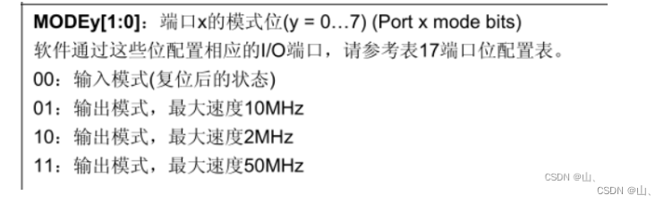
3、 Read 、 Set pin level
stay GPIO Inside , There must be data registers , Save the level data of each pin .
such as STM32F103 in , Also in GPIOx_ODR Middle configuration GPIO Output , To which bit Write 1, The corresponding pin outputs high level .
3、 ... and 、 Diode and triode
Diodes and triodes are used very frequently in circuits , Here is a brief introduction .
1、 diode
For diodes, you only need to know that diodes have unidirectional conductivity , He can only conduct in one direction .

The current can only be positive (+) Flow to negative (-).V just - V negative > VAL Then conduct .VAL It's usually 0.7v, Different materials VAL It will be different .
The protection circuit can be made by using the single conductivity of diode , For example, prevent the reverse connection of the power supply . If the power supply is connected reversely , Then the diode is not conductive , No current can be formed .
2、 triode
The triode is also conductive only under certain conditions . It is often used as a switching circuit .
The triode is divided into PNP and NPN Two kinds of , But the principle is similar .
For triodes , Just remember Through the base b And the transmitter e On control collector c And the transmitter e On of .
NPN:

Judge the current flow according to the arrow in the figure . If the base voltage Vb Greater than the emitter voltage Ve, be be There is continuity between , Which leads to ce There is continuity between . that V2 It is connected with low ,V2=0.
Usually Vb-Ve > 0.7v I think be There is continuity between , This voltage may vary depending on the material .
Vcon = 1,be Conduction ,ce Conduction ,V2 =0 Low level .
Vcon = 0,be end ,ce end ,V2 = V High level .
You can see ,V2 Voltage and Vcon The voltage is opposite , So a triode can be used as a reverse circuit .
PNP:
PNP Type triode and NPN Similar .
Judge the current flow according to the arrow in the figure . If emitter voltage Ve Greater than base voltage Vb, be eb There is continuity between , Which leads to ec There is continuity between . that V2 Just like V Connected to a ,V2=V, High level .
Vcon = 1,eb end ,ec end ,V2 =0 Low level .
Vcon = 0,eb Conduction ,ec Conduction ,V2 = V High level .
Four 、 common GPIO circuit
With LED For example , Use GPIO control LED, Generally, there are several connection methods :
1、 Direct connection LED, The chip lights up

This connection method is intuitive , Understandability . But the driving ability of chip pins may not be enough ,LED The maximum luminous intensity may not be reached .
2、 Direct connection LED, The external power supply is on

This connection method GPIO Output low level ,LED Lit by an external power supply . But when the current enters the chip too much , It may burn the chip .
3、 Use 1 Three transistor connections , High level lighting

GPIO Output high level ,LED By Vcc Lighten up , The current will not flow to the chip , So it won't burn the chip .
here GPIO Only high level can light up LED.
4、 Use 2 Three transistor connections , Low level on

GPIO Output low level ,Q2 end ,Q1 Conduction ,LED By Vcc Lighten up , The current will not flow to the chip , Will not burn the chip .
here GPIO Low level on LED.
The above four connection methods , The latter two are usually used . For other components such as buzzer 、 Keys, etc. are the same as the above LED The connection method is similar .
边栏推荐
- Summary of common mathematical knowledge
- Chaoslibrary · UE4 pit opening notes
- The use of padding.nn.bceloss
- Under the "double carbon" goal of the digital economy, why does the "digital East and digital West" data center rely on liquid cooling technology to save energy and reduce emissions?
- For loop
- LVGL8.1版本笔记
- 利用google or-tools 求解数独难题
- opencv库安装路径(别打开这个了)
- g2o安装路径记录--为了卸载
- Six trends and eight technologies of high-performance computing in data centers under "data center white paper 2022" and "computing from the east to the west"
猜你喜欢

论文解读:《利用注意力机制提高DNA的N6-甲基腺嘌呤位点的鉴定》

从已有VOC2007数据集生成yolov3所需要的数据集,以及正式开始调试程序需要修改的地方

LearnOpenGL - Introduction

Gaode positioning - the problem that the permission pop-up box does not appear

Introduction and use of Ninja

论文解读:《基于BERT和二维卷积神经网络的DNA增强子序列识别transformer结构》
Tips for using textviewdidchange of uitextview

對.h5文件的迭代顯示,h5py數據操作

Gartner调查研究:中国的数字化发展较之世界水平如何?高性能计算能否占据主导地位?

Necessary mathematical knowledge for machine learning / deep learning
随机推荐
怎么建立数据分析思维
Service Service
BST tree
with语句
The use of padding.nn.bceloss
Iterative display of.H5 files, h5py data operation
Notes | Baidu flying plasma AI talent Creation Camp: How did amazing ideas come into being?
Double ended queue
G2o installation path record -- for uninstallation
Gartner research: how is China's digital development compared with the world level? Can high-performance computing dominate?
论文解读:《基于预先训练的DNA载体和注意机制识别增强子-启动子与神经网络的相互作用》
论文解读:《开发一种基于多层深度学习的预测模型来鉴定DNA N4-甲基胞嘧啶修饰》
数据分析的重要性
知识图谱、图数据平台、图技术如何助力零售业飞速发展
Introduction and use of Ninja
Interpretation of yolov3 key code
Matplotlib Usage Summary
笔记 | 百度飞浆AI达人创造营:深度学习模型训练和关键参数调优详解
使用PyOD来进行异常值检测
Pytoch personal record (do not open)