当前位置:网站首页>[STM32 skill] use the hardware I2C of STM32 Hal library to drive rx8025t real-time clock chip
[STM32 skill] use the hardware I2C of STM32 Hal library to drive rx8025t real-time clock chip
2022-06-22 23:23:00 【Small stones have big connotations】
Basic configuration
- Use single chip microcomputer APM32F103RBT6
- Use peripherals I2C1 - PB7 SDA
- Use peripherals I2C1 - PB6 SCK
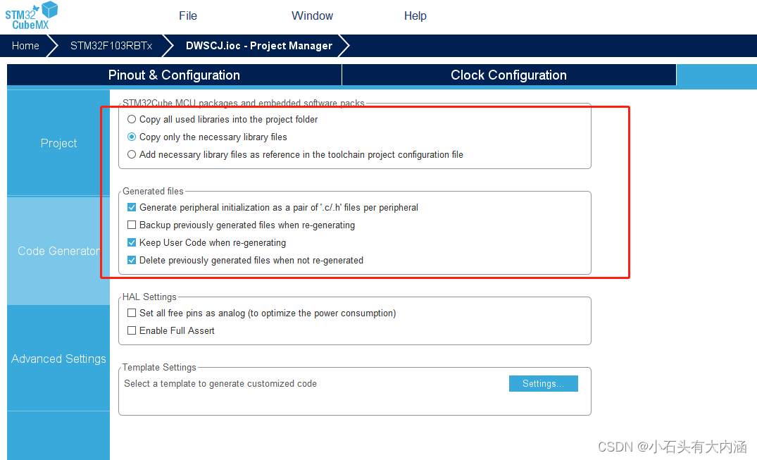
- STM32CUBEMX edition 5.6
The configuration is as follows

i2c.c file
/** ****************************************************************************** * File Name : I2C.c * Description : This file provides code for the configuration * of the I2C instances. ****************************************************************************** * @attention * * <h2><center>© Copyright (c) 2022 STMicroelectronics. * All rights reserved.</center></h2> * * This software component is licensed by ST under Ultimate Liberty license * SLA0044, the "License"; You may not use this file except in compliance with * the License. You may obtain a copy of the License at: * www.st.com/SLA0044 * ****************************************************************************** */
/* Includes ------------------------------------------------------------------*/
#include "i2c.h"
/* USER CODE BEGIN 0 */
/* USER CODE END 0 */
I2C_HandleTypeDef hi2c1;
/* I2C1 init function */
void MX_I2C1_Init(void)
{
hi2c1.Instance = I2C1;
hi2c1.Init.ClockSpeed = 100000;
hi2c1.Init.DutyCycle = I2C_DUTYCYCLE_2;
hi2c1.Init.OwnAddress1 = 0;
hi2c1.Init.AddressingMode = I2C_ADDRESSINGMODE_7BIT;
hi2c1.Init.DualAddressMode = I2C_DUALADDRESS_DISABLE;
hi2c1.Init.OwnAddress2 = 0;
hi2c1.Init.GeneralCallMode = I2C_GENERALCALL_DISABLE;
hi2c1.Init.NoStretchMode = I2C_NOSTRETCH_DISABLE;
if (HAL_I2C_Init(&hi2c1) != HAL_OK)
{
Error_Handler();
}
}
void HAL_I2C_MspInit(I2C_HandleTypeDef* i2cHandle)
{
GPIO_InitTypeDef GPIO_InitStruct = {
0};
if(i2cHandle->Instance==I2C1)
{
/* USER CODE BEGIN I2C1_MspInit 0 */
/* USER CODE END I2C1_MspInit 0 */
__HAL_RCC_GPIOB_CLK_ENABLE();
/**I2C1 GPIO Configuration PB6 ------> I2C1_SCL PB7 ------> I2C1_SDA */
GPIO_InitStruct.Pin = GPIO_PIN_6|GPIO_PIN_7;
GPIO_InitStruct.Mode = GPIO_MODE_AF_OD;
GPIO_InitStruct.Speed = GPIO_SPEED_FREQ_HIGH;
HAL_GPIO_Init(GPIOB, &GPIO_InitStruct);
/* I2C1 clock enable */
__HAL_RCC_I2C1_CLK_ENABLE();
/* USER CODE BEGIN I2C1_MspInit 1 */
/* USER CODE END I2C1_MspInit 1 */
}
}
void HAL_I2C_MspDeInit(I2C_HandleTypeDef* i2cHandle)
{
if(i2cHandle->Instance==I2C1)
{
/* USER CODE BEGIN I2C1_MspDeInit 0 */
/* USER CODE END I2C1_MspDeInit 0 */
/* Peripheral clock disable */
__HAL_RCC_I2C1_CLK_DISABLE();
/**I2C1 GPIO Configuration PB6 ------> I2C1_SCL PB7 ------> I2C1_SDA */
HAL_GPIO_DeInit(GPIOB, GPIO_PIN_6|GPIO_PIN_7);
/* USER CODE BEGIN I2C1_MspDeInit 1 */
/* USER CODE END I2C1_MspDeInit 1 */
}
}
/* USER CODE BEGIN 1 */
/******************************************************************************* * Function name : WriteI2CTData * describe : write in I2C data * Parameters : addr Device address ,reg Register address *buf Written data ,len Write length * Return value : *******************************************************************************/
HAL_StatusTypeDef WriteI2cData(uint8_t addr, uint8_t reg, uint8_t *pBuffer, uint8_t len)
{
HAL_StatusTypeDef status = HAL_OK;
status = HAL_I2C_Mem_Write(&hi2c1, addr, (uint16_t)reg, I2C_MEMADD_SIZE_8BIT, pBuffer, len, 1000);
return status;
}
/******************************************************************************* * Function name : ReadI2cData * describe : read RX8025T register * Parameters : addr Register address ,*buf Storage location ,len Read length * Return value : 1= operation failed ,0= Successful operation *******************************************************************************/
uint8_t ReadI2cData(uint8_t addr, uint8_t reg, uint8_t *buf,uint8_t len)
{
HAL_StatusTypeDef status = HAL_OK;
status = HAL_I2C_Mem_Read(&hi2c1, addr, (uint16_t)reg, I2C_MEMADD_SIZE_8BIT, buf, len, 1000);
return status;
}
/******************************************************************************* * Function name : I2cIsDeviceReady * describe : testing I2C Is the device ready to communicate * Parameters : DevAddress Device address ,Trials Number of attempts * Return value : *******************************************************************************/
HAL_StatusTypeDef I2cIsDeviceReady(uint16_t DevAddress, uint32_t Trials)
{
return (HAL_I2C_IsDeviceReady(&hi2c1, DevAddress, Trials, 1000));
}
/* USER CODE END 1 */
/************************ (C) COPYRIGHT STMicroelectronics *****END OF FILE****/
i2c.h file
/** ****************************************************************************** * File Name : I2C.h * Description : This file provides code for the configuration * of the I2C instances. ****************************************************************************** * @attention * * <h2><center>© Copyright (c) 2022 STMicroelectronics. * All rights reserved.</center></h2> * * This software component is licensed by ST under Ultimate Liberty license * SLA0044, the "License"; You may not use this file except in compliance with * the License. You may obtain a copy of the License at: * www.st.com/SLA0044 * ****************************************************************************** */
/* Define to prevent recursive inclusion -------------------------------------*/
#ifndef __i2c_H
#define __i2c_H
#ifdef __cplusplus
extern "C" {
#endif
/* Includes ------------------------------------------------------------------*/
#include "main.h"
/* USER CODE BEGIN Includes */
/* USER CODE END Includes */
extern I2C_HandleTypeDef hi2c1;
/* USER CODE BEGIN Private defines */
/* USER CODE END Private defines */
void MX_I2C1_Init(void);
/* USER CODE BEGIN Prototypes */
HAL_StatusTypeDef WriteI2cData(uint8_t addr, uint8_t reg, uint8_t *pBuffer, uint8_t len);
uint8_t ReadI2cData(uint8_t addr, uint8_t reg, uint8_t *buf,uint8_t len);
HAL_StatusTypeDef I2cIsDeviceReady(uint16_t DevAddress, uint32_t Trials);
/* USER CODE END Prototypes */
#ifdef __cplusplus
}
#endif
#endif /*__ i2c_H */
/** * @} */
/** * @} */
/************************ (C) COPYRIGHT STMicroelectronics *****END OF FILE****/
bsp_rtc.c file ( Names can be defined at will )
#include "bsp.h"
#include "app_task.h"


#define RX8025T_DEVICE_ADDRESS 0x64


/*********************************************************************************** RX8025T Real time clock driver ( Hardware IIC) BL8025T  The slave address of is  7bit  Fixed data (0110 010) When communicating , The slave address is attached to  R/W  With  8bit  Data sent . 0110 0100 Write mode ,0110 0101 For reading mode , The corresponding decimal system is :100、101; Corresponding 16 Into the system for :0x64、0x65. BL8025T  It has the function of automatically adding addresses . Once the specified starting address , Then only data bytes are sent . After each byte ,BL8025T  The address of is automatically increased . ***********************************************************************************/


/* ********************************************************************************************************* *  Letter   Count   name : bsp_InitRtc *  Functional specifications :  initial RTC.  The function is  bsp_Init()  call . *  shape   ginseng :  nothing  *  return   return   value :  nothing  ********************************************************************************************************* */
void bsp_InitRtc(void)
{


	uint8_t status;
		// The fixed cycle clock source is the minute update
	uint8_t val[3]={
    0x03,0x00,0x40};  //0x0D、0x0E、0x0F、 The values of the three registers , Set the time to update to “ second ” to update , Turn off all alarms , The warming time is 2 second , Turn on time update interrupt , Turn off other interrupts .


	status = WriteI2cData(RX8025T_DEVICE_ADDRESS, RX8025T_EXT_REG,val,3);

  printf("RX8025T set OK! %d\r\n", status);
}


/******************************************************************************* *  Function name : bsp_SetRTCAlarm *  describe  :  Set up RX8025T 's alarm clock  *  Parameters  :  Structure for storing time  *  Return value : 0 success , Other failures . *******************************************************************************/
uint8_t bsp_SetRTCAlarm(uint16_t alarm)
{

	 	uint8_t  status;
		uint8_t  value = 0;
		uint8_t  reg_cy1[2];// Alarm fixed period register
		uint8_t  reg[3];
// uint8_t buf[5];
/*  Fixed cycle timer configuration   First the TIE Set up “0”, To avoid unexpected hardware interrupts while configuring fixed cycle interrupts . (1)  Set up TSEL1,0 Select the countdown period by two digits . (2)  Set up B,C register , Thus, the initial value of the subtraction counter is set , Then initialize TF Mark is “0”. (3)  Set up TIE,TE Position as “1” */
			value = 0x40;
			status = WriteI2cData(RX8025T_DEVICE_ADDRESS, RX8025T_CONT_REG, &value, 1);

			value = 0x00;
			status = WriteI2cData(RX8025T_DEVICE_ADDRESS, RX8025T_EXT_REG, &value, 1);

			reg_cy1[0] = alarm & 0xFF;
			reg_cy1[1] = (alarm >> 8) & 0xFF;
			status = WriteI2cData(RX8025T_DEVICE_ADDRESS, RX8025T_CYl_REG, reg_cy1, 2);

			reg[0] = 0x13;		// Minutes update
			reg[1] = 0x10;
			reg[2] = 0x50;
			status = WriteI2cData(RX8025T_DEVICE_ADDRESS, RX8025T_EXT_REG, reg, 3);

			return status;

}

/******************************************************************************* *  Function name : bsp_GetRtcTime *  describe  :  from RX8025T Acquisition time  *  Parameters  :  Structure for storing time  *  Return value : 0 success ,1 Failure . *******************************************************************************/
uint8_t bsp_GetRtcTime(TIME_T *t)
{

	uint8_t rtc_str[7];

	if(ReadI2cData(RX8025T_DEVICE_ADDRESS, RX8025T_SEC_REG, rtc_str,7) != 0)  // Get date and time
		return 1;  // Read error

	t->second = ((rtc_str[0]>>4)*10) + (rtc_str[0] & 0x0f);
	t->minute = ((rtc_str[1]>>4)*10) + (rtc_str[1] & 0x0f);
	t->hour   = ((rtc_str[2]>>4)*10) + (rtc_str[2] & 0x0f);
	t->week		= rtc_str[3];
	t->day    = ((rtc_str[4]>>4)*10) + (rtc_str[4] & 0x0f);
	t->month  = ((rtc_str[5]>>4)*10) + (rtc_str[5] & 0x0f);
  t->year   = ((rtc_str[6]>>4)*10) + (rtc_str[6] & 0x0f);

	return 0;
}

/******************************************************************************* *  Function name : bsp_SetRtcTime *  describe  :  Set up RX8025T Time  *  Parameters  :  Structure for storing time  *  Return value : 0 success ,1 Failure . *******************************************************************************/
uint8_t bsp_SetRtcTime(TIME_T *t)
{

		uint8_t  status;
		uint8_t rtc_str[7];

		rtc_str[0] = ((t->second/10)<<4) | (t->second%10);
		rtc_str[1] = ((t->minute/10)<<4) | (t->minute%10);
		rtc_str[2] = ((t->hour/10)<<4) | (t->hour%10);
		rtc_str[3] = t->week;
		rtc_str[4] = ((t->day/10)<<4) | (t->day%10);
		rtc_str[5] = ((t->month/10)<<4) | (t->month%10);
		rtc_str[6] = ((t->year/10)<<4) | (t->year%10);


		status = WriteI2cData(RX8025T_DEVICE_ADDRESS, RX8025T_SEC_REG, rtc_str, 7);
		return status;
}
bsp_rtc.h file ( Names can be defined at will )
#ifndef _BSP_RTC_H_
#define _BSP_RTC_H_


#define RX8025T_SEC_REG 0x00 // second
#define RX8025T_MIN_REG 0x01 // branch
#define RX8025T_HOU_REG 0x02 // when
#define RX8025T_WEE_REG 0x03 // week ,bit0~bit7 Corresponding day 、 One 、 Two 、 3、 ... and 、 Four 、 5、 ... and 、 6、 ... and , The corresponding value is 0x01,0x02,0x04,0x08,0x10,0x20,0x40, Do not appear 2 Position as 1 The situation of .
#define RX8025T_DAY_REG 0x04 // date
#define RX8025T_MON_REG 0x05 // month
#define RX8025T_YEA_REG 0x06 // year
#define RX8025T_RAM_REG 0x07 //RAM

#define RX8025T_ALm_REG 0x08 // Alarm clock minute , No, it can be ram Use .
#define RX8025T_ALh_REG 0x09 // Alarm clock hour , No, it can be ram Use .

#define RX8025T_ALw_REG 0x0a // Alarm clock week , No, it can be ram Use .
#define RX8025T_CYl_REG 0x0b // Cycle timer low 8 position
#define RX8025T_CYm_REG 0x0c // Cycle timer high 4 position , Cycle timers total 12 position .

#define RX8025T_EXT_REG 0x0d // Extended registers ,bit7-TEST= Factory testing , Always write 0;bit6-WADA= Week or calendar alarm selection bit ;bit5-USEL= Select second or minute update to trigger update interrupt ,0= Second update ,1= Minutes update ;
																		        //bit4-TE= Periodic timing enable ;bit3\2-FSEL1\0= chip FOUT Pin output frequency selection bit ;bit1\0-TSEL1\0= Internal clock source used to set a fixed period .

#define RX8025T_FLAG_REG 0x0e // Flag register ,bit5-UF,bit4-TF,bit3-AF, Time update interrupt , Fixed cycle timing interrupt , Interrupt flag bit of alarm clock interrupt ;bit1-VLF Low voltage ,bit0-VDET Stop working flag bit due to voltage low temperature compensation .

#define RX8025T_CONT_REG 0x0f // Control register ,bit6~7(CSEL0、1)= Temperature compensation interval setting ;bit5(UIE)= Time update interrupt enable bit ( May by D The register of USEL Bit configuration is 1 Second update or 1 Minutes update );


#define TESL1_0_CLOCK_4069 0
#define TESL1_0_CLOCK_64 1
#define TESL1_0_CLOCK_S 2
#define TESL1_0_CLOCK_M 3


//TE  position   This bit is used to control the enable of the fixed cycle timing function .
// Set up “1” Select to enable the fixed cycle timing function .
// Set up “0” Select to turn off the fixed cycle timing function .
#define TE_1 1<<4
#define TE_0 (~(1<<4))


#define TF_1 1<<4
#define TF_0 (~(1<<4))


#define TF_FLAG 0x10


// Timer interrupt enable bit
#define TIE_1 1<<4
#define TIE_0 (~(1<<4))


typedef struct  // _TIME
{

	uint8_t second;
	uint8_t minute;
	uint8_t hour;
	uint8_t week;
	uint8_t day;
	uint8_t month;
	uint8_t year;
	uint8_t reserve;
}TIME_T;


void bsp_InitRtc(void);
uint8_t bsp_SetRTCAlarm(uint16_t alarm);
uint8_t bsp_SetRtcTime(TIME_T *t);
uint8_t bsp_GetRtcTime(TIME_T *t);


#endif
边栏推荐
- OJ每日一练——单词的长度
- 剑指 Offer 11. 旋转数组的最小数字
- 安装typescript环境并开启VSCode自动监视编译ts文件为js文件
- 2020-12-04
- 14. 最长公共前缀
- Autoincrement attribute of sqlserver replication table
- MySQL master-slave synchronization and its basic process of database and table division
- Digital data was invited to participate in Nantong enterprise digital transformation Seminar
- C sqlsugar, hisql, FreeSQL ORM framework all-round performance test vs. sqlserver performance test
- Is it safe to make an appointment to pay new debts? Is it reliable?
猜你喜欢

mysql主从同步及其分库分表基本流程

Digital data depth | about software self-control, source code left, no code right

保证数据库和缓存的一致性

SourceTree版本管理常用操作

在Word中自定义多级列表样式
Ensure database and cache consistency

Asynchronous FIFO

Smart data won two annual awards at the second isig China Industrial Intelligence Conference

2021-08-21

three.js模拟驾驶游览艺术展厅---打造超级相机控制器
随机推荐
优化——线性规划
LeakCanary 源码详解(2)
LeetCode_ Backtracking_ Dynamic programming_ Medium_ 131. split palindrome string
mysql主从同步及其分库分表基本流程
Spark RDD Programming Guide(2.4.3)
Finding the value of the nth term of Fibonacci sequence by recursion
Three cache methods and principles
Summary of transport layer knowledge points
Spark SQL 访问json和jdbc数据源
OJ每日一练——删除单词后缀
Digital data was invited to participate in Nantong enterprise digital transformation Seminar
Introduction to database access tools
C sqlsugar, hisql, FreeSQL ORM framework all-round performance test vs. sqlserver performance test
Greedy interval problem (2)
Spark SQL Generic Load/Save Functions(2.4.3)
Smart data won two annual awards at the second isig China Industrial Intelligence Conference
[kubernetes series] overview of kubernetes
获取当前所在周的起始和结束的日期
好东西要分享啦
js读取剪切板的图片