当前位置:网站首页>Summary of several common UML diagrams
Summary of several common UML diagrams
2022-06-26 18:42:00 【JobsTribe】
stay UML Of
Class diagram in , There are several common relationships : generalization (Generalization), Realization (Realization), relation (Association), polymerization (Aggregation), Combine (Composition), rely on (Dependency)
1. generalization (Generalization)
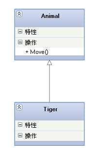
【 Generalization relation 】: It's an inheritance relationship , To express a general or special relationship , It specifies how the subclass can specialize all the features and behaviors of the parent class . for example : Tiger is a kind of animal , There are not only tiger's characteristics, but also animal's common characteristics .
【 The arrow points to 】: A solid line with a triangular arrow , The arrow points to the parent class
2. Realization (Realization)
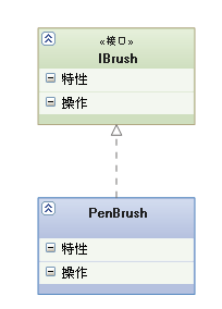
【 Realization relationship 】: It's a kind of interface relationship , A presentation class is an implementation of all the features and behaviors of an interface .
【 The arrow points to 】: Dotted line with triangular arrows , The arrow points to the interface
3. relation (Association)
【 Connections 】: It's a relationship of ownership , It lets one class know the properties and methods of another class ; Such as : Teachers and students , Husband and wife
Association can be two-way , It could be one-way . A two-way association can have two arrows or no arrows , A one-way association has an arrow .
【 The code is 】: Member variables
【 Arrows and points 】: With normal arrow ( Or black triangle arrow ) Solid line for , Point to the possessed

Above picture , Teachers and students are connected in two ways , The teacher has many students , Students may also have more than one teacher . But the relationship between students and a course is unidirectional , A student may take more than one course , Course is an abstract thing. He doesn't have students .
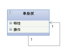
The picture above shows the self relevance :
4. polymerization (Aggregation)
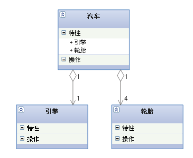
【 Aggregate relationship 】: It's the relationship between the whole and the part , And the part can leave the whole and exist alone . For example, the relationship between the car and the tire is the relationship between the whole and the part , The tires can still be left in the car .
Aggregation is a kind of association , It's a strong correlation ; Association and aggregation are grammatically indistinguishable , We must examine the concrete logical relations .
【 The code is 】: Member variables
【 Arrows and points 】: A solid line with a hollow diamond , Rhombus pointing to the whole
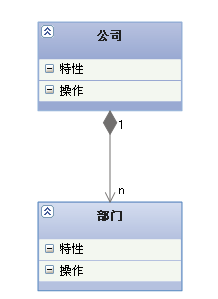
5. Combine (Composition)
【 synthetic relation 】: It's the relationship between the whole and the part , But part cannot exist alone without the whole . For example, the relationship between the company and the Department is the whole and part , There is no department without a company .
A combination relationship is a kind of association relationship , It's a stronger relationship than an aggregate relationship , It requires that the object representing the whole in the common aggregation relationship is responsible for the life cycle of the object representing the part
【 The code is 】: Member variables
【 Arrows and points 】: A solid line with a solid diamond , Rhombus pointing to the whole
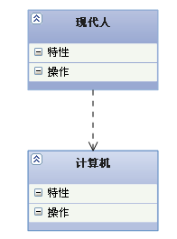
6. rely on (Dependency)
【 Dependency relationship 】: It's a relationship of use , That is, the implementation of one class needs the assistance of another class , So try not to use two-way interdependence .
【 Code representation 】: local variable 、 Method parameters or calls to static methods
【 Arrows and points 】: Dotted line with arrow , Point to the user
The order of strength and weakness of various relationships :
generalization = Realization > Combine > polymerization > relation > rely on
This picture below UML chart , It vividly shows all kinds of class diagram relationships :

====================================================
Sequence diagram It is mainly used to show the order of interaction between objects .
Sequence diagrams represent interactions as a two-dimensional graph . The vertical is the time axis , Time goes down the vertical line . The horizontal axis represents the class element role of each independent object in collaboration . Class element roles are represented by lifelines . When an object exists , Characters are represented by a dotted line , When the process of an object is active , The lifeline is a two lane line .
Messages are represented by arrows from the lifeline of one object to the lifeline of another . The arrows are arranged in chronological order from top to bottom in the diagram .
The elements involved in the sequence diagram :
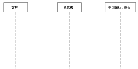
1. Lifeline :
Lifeline names can be underlined . When using underscores , It means that the lifeline in the sequence diagram represents a specific entity of a class .
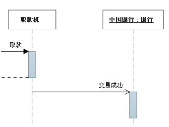
2. Sync message
The sender before it continues , Will wait for synchronous message response
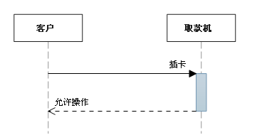
3. Asynchronous messaging
Before the sender continues , No need to wait for a response message
4. notes

5. constraint
The sign of the constraint is simple ; The format is : [Boolean Test]

6. Combining fragments
Combining fragments It is used to solve the conditions and methods of interactive execution . It allows direct representation of logical components in sequence diagrams , Used to specify the application area of a condition or subprocess , Define special conditions and subprocesses for any part of any lifeline .
The common combination fragments are :
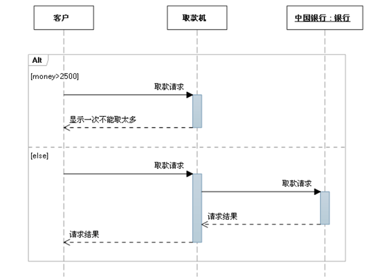
a. Choose (Alt)
Choices are used to indicate mutually exclusive choices between two or more message sequences , Equivalent to the classic if..else...
There is only one sequence of choices in any situation . You can set a threshold in each fragment to indicate the conditions under which the fragment can run . else It means that none of the other thresholds is True The fragment that should be run when . If all the criticalities are False And there's no else, No fragments are executed .
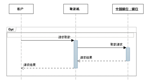
b. Options (Opt)
Contains a sequence that may or may not occur
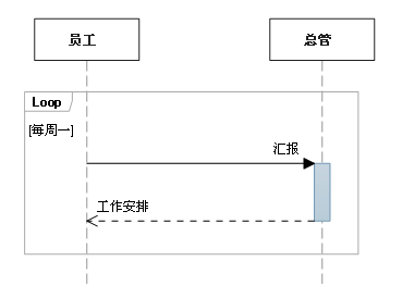
c. loop (Loop)
Repeat the fragment a certain number of times . The condition of fragment repetition can be indicated in criticality .
d. parallel (Par)
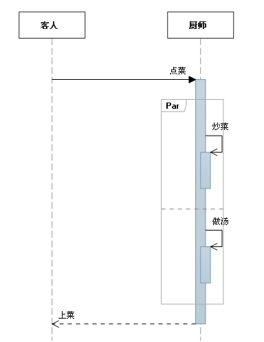
The following table lists the commonly used combination fragments :
Fragment type | name | explain |
Opt | Options | Contains a sequence that may or may not occur . The conditions under which the sequence occurs can be specified in criticality . |
Alt | Choose | Contains a list of fragments , These fragments contain alternative message sequences . In any case, there is only one sequence . You can set a threshold in each fragment to indicate the conditions under which the fragment can run . else It means that none of the other thresholds is True The fragment that should be run when . If all the criticalities are False And there's no else, No fragments are executed . |
Loop | loop | Repeat the fragment a certain number of times . The condition of fragment repetition can be indicated in criticality . Loop The combined fragment has “Min” and “Max” attribute , They indicate the minimum and maximum number of times a fragment can be repeated . The default is unlimited . |
Break | interrupt | If you execute this fragment , Then discard the rest of the sequence . Criticality can be used to indicate the condition under which an interrupt occurs . |
Par | parallel | parallel processing . The events in the fragment can be interleaved . |
Critical | The key | Use in Par or Seq In the clip . Indicates that messages in this fragment must not be interleaved with other messages . |
Seq | Weak order | There are two or more fragments of operands . Messages involving the same lifeline must occur in fragment order . If the lifeline involved in the message is different , Messages from different fragments may be interleaved in parallel . |
Strict | Strong order | There are two or more fragments of operands . These fragments must occur in a given order . |
About how to interpret fragments of sequences
By default , The sequence diagram shows a series of messages that can happen . In the running system , Other messages may appear that you did not choose to display on the diagram .
The following fragment types can be used to change this definition :
Fragment type | name | explain |
Consider | consider | Specify the list of messages described by this fragment . Other messages can occur in the running system , But it doesn't make much sense to describe it . stay “Messages” Property, type the list . |
Ignore | Ignore | A list of messages not described in this fragment . These messages can occur in a running system , But it doesn't make much sense to describe it . stay “Messages” Property, type the list . |
Assert | Assertion | The operand fragment specifies a unique valid sequence . Usually used in Consider or Ignore In the clip . |
Neg | no | The sequence shown in this fragment must not occur . Usually used in Consider or Ignore In the clip . |
====================================================
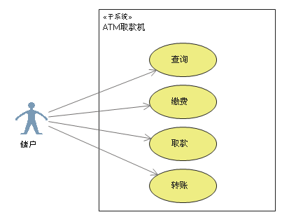
Use case diagrams are mainly used to describe user 、 demand 、 System function unit The relationship between . It shows a system function model diagram that can be observed by an external user .
【 purpose 】: Help the development team understand the functional requirements of the system in a visual way .
Use case diagram The elements included are as follows :
1. participants (Actor)
Represents the user who interacts with your application or system 、 Organization or external system . It's represented by a villain .

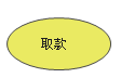
2. Use cases (Use Case)
A use case is an externally visible system function , Describe the services provided by the system . Use an ellipse to represent
3. Subsystem (Subsystem)
It's used to show part of the function of the system , This part of the function is closely linked .
4. Relationship
The relationships involved in use case diagrams are : relation 、 generalization 、 contain 、 Expand ;
As shown in the following table :
Type of relationship | explain | A symbol |
relation | The relationship between actors and use cases |
|
generalization | Relationships between actors or between use cases |
|
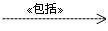
contain | The relationship between use cases |
|
Expand | The relationship between use cases |
|


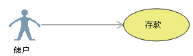
a. relation (Association)
Represents communication between actors and use cases , Either party can send or receive messages .
【 The arrow points to 】: Point to the message receiver
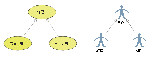
b. generalization (Inheritance)
It is generally understood as inheritance , The child use case is similar to the parent use case , But show more special behavior ; The child use case will inherit all the structure of the parent use case 、 Behavior and relationships . A child use case can use a piece of behavior from the parent use case , It can also be overloaded . The parent use case is usually abstract .
【 The arrow points to 】: Point to the parent use case
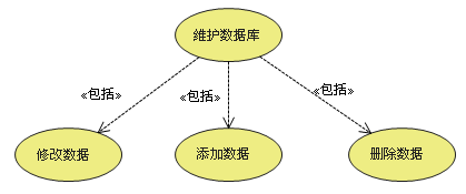
c. contain (Include)
Inclusion relation is used to decompose the function represented by a more complex use case into smaller steps ;
【 The arrow points to 】: Point to the decomposed function use cases
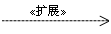
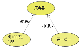
d. Expand (Extend)
Extended relationships refer to Extension of use case function , It's equivalent to providing an additional function for the base use case .
【 The arrow points to 】: Point to the underlying use case
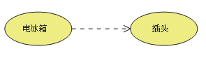
e. rely on (Dependency)
above 4 China relations , yes UML The standard relationship of definition . but VS2010 In the use case model diagram of , Added dependency , Use dotted lines with arrows to indicate
Indicates that the source use case depends on the target use case ;
【 The arrow points to 】: Point to the dependent
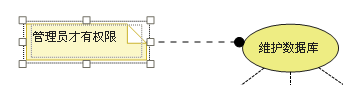
5. project (Artifact)
Use case diagrams are used to help people understand functional requirements vividly , But not many people can understand it . Most of the time, I communicate with users and even use Excel Better than the use case diagram ,VS2010 Introduced in “ project ” Such an element , So that developers can link a common document in the use case diagram .
Use dependencies to attach a use case to a project

And then put the project -》 attribute Of Hyperlink Set to your document
So when you're on the use case diagram When you double-click an item , The associated document opens .
6. notes (Comment)
contain (include)、 Expand (extend)、 generalization (Inheritance) The difference between :
Conditionality : Sub use cases and include The included examples in will happen unconditionally , and extend The occurrence of extended use cases in is conditional ;
Directness : Sub use cases and extend The extended use cases in provide direct services to participants , and include The use cases included in provide indirect services to participants .
Yes extend for , The extended use case does not contain the content of the base use case , The basic use case does not contain the content of the extended use case .
Yes Inheritance for , The sub use case contains all the contents of the basic use case and its relationship with other use cases or participants ;
An example of a use case diagram :
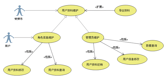
Complaining :
I feel like the use case diagram is not mature yet , It doesn't express the requirements of the system very well , No, UML Users of the background hardly know what to draw .
secondly , Inclusion relation 、 Extended relationship The arrow symbol of is the same arrow , Just write a word on the top to distinguish , Translated into other languages , I hardly know what it means . It's also hard to understand the direction of the arrow that extends the relationship , Why point to base use cases , It doesn't point to extended use cases
VS2010 Added “ project ” Elements , It's a great innovation , Be able to relate... In use case diagrams word,excel These documents . But why not integrate these functions directly into use cases , Double click on the use case to pop up a document, isn't it easier to understand , We have to add a component to it , Just to provide a link function .
Use case description table :
Since the functional requirements can not be clearly expressed by nomograph , In development, we usually use description tables to supplement some use cases that are not easy to express , The table below provides a reference for you :

边栏推荐
- Decompilation of zero time technology smart contract security series articles
- IK分词器
- redis 基础知识
- 8VC Venture Cup 2017 - Final Round C. Nikita and stack
- Installation and use of logstash
- Pinda general permission system (day 1~day 2)
- wm_concat()和group_concat()函数
- 元宇宙链游开发案例版 NFT元宇宙链游系统开发技术分析
- Comparing the size relationship between two objects turns out to be so fancy
- LeetCode 128最长连续序列
猜你喜欢

一些基本错误

Microservice architecture

In and exceptions, count (*) query optimization

Tag dynamic programming - preliminary knowledge for question brushing -2 0-1 knapsack theory foundation and two-dimensional array solution template

Wechat applet custom pop-up components
ARM裸板调试之串口打印及栈初步分析
Convex hull problem

爬取豆瓣读书Top250,导入sqlist数据库(或excel表格)中

SSO微服务工程中用户行为日志的记录

Solidity - contract inheritance sub contract contains constructor errors and one contract calls the view function of another contract to charge gas fees
随机推荐
读书笔记:《过程咨询 III》
刻录光盘的程序步骤
ros::spinOnce()和ros::spin()的使用和区别
Clion编译catkin_ws(ROS工作空间包的简称)加载CMakeLists.txt出现的问题
Eigen库计算两个向量夹角
JSONUtils工具类(基于alibaba fastjson)
ROS查询话题具体内容常用指令
Convex hull problem
CD-CompactDisk
vuex中利用缓存解决刷新state数据丢失问题
SSO微服务工程中用户行为日志的记录
Logstash安装及使用
When does the mobile phone video roll off?
gdb安装
Preliminary analysis of serial port printing and stack for arm bare board debugging
Conditional compilation in precompiling instructions
Take you to resolve hash conflicts and implement a simple hash table,
字符串String转换为jsonArray并解析
Xlua get button registration click event of ugui
ISO documents