当前位置:网站首页>ADC digital DGND, analog agnd mystery!
ADC digital DGND, analog agnd mystery!
2022-06-23 16:39:00 【Engineers see the sea】
Yesterday I wrote an article about analog and digital processing , Easy to understand :
《 Simulate 、 Digitally 、 Main land , Yours PCB Is the ground wire right ? actually ....》
Share a piece today ADI Advanced articles , It's written in depth , It is recommended to collect reading .
brief introduction
Nowadays, mixed signal devices are widely used in signal processing systems , For example, analog-to-digital converter (ADC)、 Digital to analog converter (DAC) And a fast signal processor (DSP). To process analog signals with a wide dynamic range , High speed and high performance ADC and DAC Signals are more important . In order to maintain wide dynamic range and low noise of analog signal in harsh digital environment , It is necessary to use good high-speed circuit design technology , Include proper signal routing 、 Decoupling and grounding .
in the past ,“ High precision , low speed ” Circuits are generally considered to be associated with so-called “ High speed ” The circuit is different . about ADC and DAC, Sampling rate ( about ADC Come on ) And update rate ( about DAC Come on ) As a division, it is called “ High speed ” and “ low speed ” Standards for . however , The following two examples show , Most signal processing chips today are real “ High speed ” chip , And it must be treated as a high-speed device to maintain its high performance . for example DSP and AD/DA chip .
Sampling for all signal processing applications ADC( With an internal sample and hold circuit ADC) Both operate with relatively high-speed clocks . The clock has fast rising and falling time ( Usually a few nanoseconds ), So it must be regarded as a high-speed device , Even though the conversion rate may be low . for example , A medium speed 12 Bit successive approximation (SAR)ADC But in the 10MHz Working on the internal clock of , The sampling rate is only 500 KSPS.
Σ-Δ ADC High speed clock is also required , Because they have a high oversampling rate . Even high resolution 、 So-called “ Low frequency ” Industrial measurement Σ-Δ ADC( Throughput for 10 Hz to 7.5 kHz) Also in the 5MHz Or higher clock frequency , To provide 24 Bit resolution ( for example ,ADI The company's AD77xx - series ).
More complicated is , Mixed signal IC It has analog and digital ports , Therefore, how to use appropriate grounding technology is even more at a loss . Besides , Mixed signal IC Some have relatively low digital current , Others have high digital currents . In many cases , The two types must be treated differently , In order to achieve the best grounding .
Digital and analog design engineers tend to treat mixed signal equipment from different perspectives , The purpose of this tutorial is to summarize a general grounding principle , It can be used in most mixed signal equipment , Without knowing the details of its internal circuit .
Grounding layer and power layer
Low impedance 、 Large area ground plane is very important for analog circuit and digital circuit . The ground plane is not only for supplying high-frequency current ( High speed digital logic ) A low impedance return path , And minimize EMI / RFI radiation . Due to the shielding effect of the ground plane , The circuit is external EMI / RFI The sensitivity of .
The ground plane also allows the use of transmission line technology that requires controllable impedance ( Microstrip or stripline ) To transmit high-speed digital or analog signals .
because “ a bus or bus bar (buss wire)” It has impedance at most logic conversion equivalent frequencies , Use it as “ The earth ” It's totally unacceptable . for example ,#22 The standard conductor has about 20 nH/ Inch inductance . The swing rate generated by the logic signal is 10mA/ns Transient current , Flow through at this frequency 1 Inch this wire will form 200 mV Useless pressure drop :
Those who have 2 V Peak to peak range signal , This pressure drop translates into approximately 10% The error of the ( about 3.5 Bit accuracy ). Even in all digital circuits , This error will lead to a significant reduction in the logic circuit noise margin .
chart 1 : The digital current flowing into the analog return path generates an error voltage
chart 1 It shows that the digital return current interferes with the analog return current ( Top view ) A typical example of . The conductor inductance and resistance of the grounding path are shared by analog and digital circuits , This will have an interaction , Eventually, errors will occur . One possible solution is to let the digital circuit current flow directly to the return path GND REF, As shown in the bottom drawing . This is a “ Star grounding ” Or the basic principle of single point grounding . It is very difficult to realize real single point grounding in a system with multiple high-frequency return paths , Because the physical length of the individual current return path leads to parasitic resistance and inductance , This does not conform to the low impedance grounding principle of high frequency current . In practice , The current loop must consist of a large area of ground plane , So as to realize low impedance grounding under high frequency current . If there is no low impedance ground plane , It is almost impossible to avoid the above shared impedance , Especially at high frequencies .
All integrated circuit grounding pins shall be directly connected to the low impedance ground plane , This minimizes the series inductance and resistance ( Don't use anything IC Seats and so on ). For high-speed devices , Traditional... Is not recommended IC slot . Even if it's “ Small size ” slot , Additional inductance and capacitance may also introduce unwanted shared paths , Thus, the device performance is damaged . If the slot must fit DIP Package use , For example, when making prototypes , individual “ Pin slots ” or “ Cage socket ” It is acceptable . The above pin slots are available in both capped and uncapped versions (AMP Product model 5-330808-3 and 5-330808-6). Due to the use of spring metal contacts , Ensured IC The pins have good electrical and mechanical connections . however , Repeated plugging and unplugging may reduce its performance .
Decoupling of low frequency and high frequency
Each power supply is entering PC Board time , It shall be decoupled to the low impedance ground plane by a large capacity electrolytic capacitor , And the electrolytic capacitor is close to the power terminal . This will minimize the low-frequency noise on the power line . At each individual analog level , various IC The encapsulated power supply pins need to be locally filtered only for high frequencies ( It means that we often use 104 Capacitor bypass chip , Note that not all cases use 100nF Of .20MHz The following is used 100nF, The higher the frequency, the smaller the capacitance ).
chart 2 : The local high frequency power filter passes through a short low inductance path ( Ground plane ) Provides optimal filtering and decoupling
chart 2 Shows this method , The left side of the figure shows the correct implementation scheme , On the right is the wrong implementation plan . In the example on the left , Typical 0.1 μF The chip ceramic capacitor is directly connected to the through hole PCB Ground plane on the back , And connected to through the second via IC Of GND On the pin . by comparison , The setting on the right is not ideal , An additional... Is added to the ground path of the decoupling capacitor PCB Wiring inductance , Reduce effectiveness .( If possible, it is better to put the chip capacitor directly below the back of the chip .)
All the high-speed chips ( Frequency greater than 10MHz) You need something like figure 2 Connected bypass capacitor to achieve good performance . The magnetic beads here are not 100% necessary , But it will enhance the isolation and decoupling of high-frequency noise , Usually more advantageous . It may be necessary to verify whether the magnetic beads will be in IC Saturation when handling high currents .
Please note that , For some magnetic beads , Even before saturation occurs , Some magnetic beads may already be nonlinear , So if you need a power stage to work with a low distortion output , This should also be checked and verified .
Double and multi layers PCB
Every PCB At least one complete layer shall be dedicated to grounding . Ideally , One side of the double-sided circuit board shall be completely used for the ground plane , The other side is used for interconnection . But in practice , It's impossible , Because part of the ground plane must be removed for the crossing of signal and power supply 、 Through hole and through hole . For all that , Or we should save as much area as possible , At least keep 75%. After completing the initial layout , Please check the ground plane carefully , Make sure there is no isolated ground “ Isolated island ”( Similar to dead copper ), Because it is located in the grounding “ Isolated island ” Internal IC The ground pin has no current return path to the ground plane . In addition, check whether there is weak connection between adjacent large areas of the ground plane , Otherwise, the effectiveness of the ground plane may be greatly reduced . without doubt , Automatic wiring technology is generally not suitable for the design of mixed signal circuit boards , Therefore, it is strongly recommended to route manually
Surface mount IC There are a lot of interconnections in high-density integrated systems , Multilayer circuit boards must be used . such , At least one full floor may be dedicated to earthing . ordinary 4 The layer circuit board has internal grounding and power layer , The outer two layers are used for the interconnection of surface mount components . The power layer and the ground layer are adjacent to each other to provide additional interlayer capacitance ( At present, no discrete component can achieve the effect of interlayer capacitance ), Contribute to high frequency decoupling of power supply . In most systems ,4 Layers are not enough , Other layers are also required for signal and power wiring .
Multi card mixed signal system
In a multi card system , The best way to reduce the grounding impedance is to use “ Motherboard ”PCB As an inter Card Interconnect backplane , This provides a continuous ground plane for the backplane .PCB The pins of the connector shall have at least 30 to 40% Dedicated for grounding , These pins should be connected to the ground plane on the backplane motherboard .
chart 3 : Multipoint grounding concept
Last , There are two possible ways to realize the overall system grounding scheme :
1、 The backplane ground plane can be connected to the chassis ground through multiple points , Thus, various ground current return paths are diffused . This method is often referred to as “ Multipoint ” Grounding system , Pictured 3 Shown .
2、 The ground plane can be connected to a single system “ Star grounding ” spot ( Generally located in the power supply ).
The first method is most commonly used in all digital systems , But it can be used in mixed signal system , The premise is that the grounding current generated by the digital circuit is low enough , And spread over a large area .PC plate 、 Backplane 、 The chassis maintains a low resistance path . however , Good electrical contact is essential where the ground is connected to the sheet metal chassis . This requires tapping screws ( It is the kind of common pointed screw that is tightened more and more every month ) And snap washers . The casing is made of anodized aluminum ( The shell surface is coated with a layer of aluminum oxide , Non conducting ) Special care must be taken when , At this time, the casing table is the insulator ( This method is not feasible ).
The second method (“ Star grounding ”) It is usually used in high-speed mixed signal systems with independent analog and digital terrestrial systems , And need further discussion .
Separate analog and digital ground planes
In the mixed signal system using a large number of digital circuits , It is better to physically separate sensitive analog components from multi noise digital components . It is also advantageous to use separate ground planes for analog and digital circuits . Avoiding overlap minimizes capacitive coupling between the two . Separate analog and digital ground planes are connected to the ground plane through the motherboard or “ Grounding grid ”( It consists of a series of wired interconnections between the grounding pins of the connector ), Continue to extend on the backplane . Pictured 4 Shown , The two layers remain separate , Until we return to the common system “ Star type ” Grounding , Generally located at the power port . Ground plane 、 Power supply and “ Star type ” The connection between the earthing shall be made of multiple overall bars or wide copper webbing , In order to obtain the minimum resistance and inductance . Every PCB Insert the back-to-back Schottky diode on the , To prevent accidental DC voltage between two grounded systems when inserting and removing the card . This voltage should be less than 300 mV, In order to avoid damage to both analog and digital ground planes IC. Schottky diode is recommended , It has low capacitance and low forward voltage drop . Low capacitance prevents AC coupling between analog and digital ground planes . Schottky diode at about 300 mV Start conducting electricity , If high current is expected , Several diodes in parallel may be required . In some cases , Magnetic beads can replace Schottky diodes , However, DC grounding loop will be introduced , It will be troublesome in a high-precision system .
chart 4 : Separate analog and digital ground planes
The ground plane impedance must be as low as possible , Until it returns to the system star grounding . The distance between two ground planes is higher than 300 mV DC or AC voltage will not only damage IC, It will also lead to false triggering of logic gates and possible locking .
Mixed signal with low digital current IC Grounding and decoupling of
Sensitive analog components such as amplifiers and voltage references are always referenced and decoupled to the analog ground plane . Low digital current ADC and DAC( And other mixed signals IC) It should generally be considered a simulator , It can also be grounded and decoupled to the analog ground plane . At first glance , This requirement seems somewhat contradictory , Because the converter has analog and digital interfaces , And usually designated as analog grounding (AGND) And digital grounding (DGND) The pin of . chart 5 The illustrations in help to explain this apparent dilemma .
chart 5 : Mixed signal with low internal digital current IC Proper grounding of the
Having both analog and digital circuits IC( for example ADC or DAC) Inside , The ground port usually remains independent , Avoid coupling digital signals into analog circuits . chart 5 Shows a simple converter model . Connecting the chip pad to the package pin will inevitably produce wire bonding inductance and resistance ,IC There is nothing designers can do about it , Just be clear in your heart . The rapidly changing digital current is B Point generates voltage , And must pass through stray capacitance CSTRAY A circuit coupled to an analog circuit A spot . Besides ,IC There are about... Between each pin of the package 0.2pF Stray capacitance , It's also inevitable !IC The designer's task is to eliminate this influence and make the chip work normally . however , To prevent further coupling ,AGND and DGND It shall be connected externally by the shortest lead , And connected to the simulated ground plane .DGND Any additional impedance in the connection will be at B Points produce more digital noise , In turn, more digital noise is coupled to the analog circuit through stray capacitance . Please note that , take DGND Connecting to the digital ground plane will be at AGND and DGND Apply... At both ends of the pin VNOISE, Cause serious problems !
IC Upper “DGND” The name indicates that this pin is connected to IC Digital earth , However, this does not mean that this pin must be connected to the digital ground of the system .
This arrangement may indeed inject a small amount of digital noise into the analog ground plane . But these currents are very small , Just make sure that the converter output does not drive a large fan out ( This is not usually the case ) Can be minimized . Minimize fan out on the converter digital port , It can also make the converter logic conversion less affected by ringing , Minimize digital switching current , This reduces the possibility of coupling to the converter analog port . By inserting small lossy ferrite beads , Pictured 5 Shown , Logic power pin (VD) It can be further isolated from the analog power supply . The internal transient digital current of the converter will flow in the small loop , from VD Arrive at... Through decoupling capacitor DGND( This path is represented by a thick solid line in the figure ). Therefore, the transient digital current will not appear on the external analog ground plane , But confined to the loop .VD The pin decoupling capacitor should be installed as close to the converter as possible , To minimize parasitic inductance . These decoupling capacitors shall be of the low inductance ceramic type , Usually between 0.01 μF and 0.1 μF Between .
Handle with care ADC Digital output
Place the buffer register next to the converter ( Pictured 5 Shown ) It is a good way , The converter digital line can be isolated from the noise on the data bus . Buffer registers also help minimize the load on the converter's digital output , It also provides Faraday shielding between digital output and data bus . Although many converters have three state outputs / Input , But this isolation register still represents a good design method . In some cases , It may be necessary to add additional buffer registers on the analog ground plane next to the converter output , To provide better isolation .
ADC The series resistance between the output and the input of the buffer register ( chart 5 Marked as “R”) Helps minimize digital transient currents , These currents may affect converter performance . The resistor separates the digital output driver from the capacitor of the buffer register input . Besides , It is composed of series resistance and buffer register input capacitance RC The network is used as a low-pass filter , To slow down the fast edges .
A typical CMOS Grid and PCB Wiring and through holes are combined , Will produce about 10 pF The load of . If there is no isolation resistance ,1 V/ns The logic output slew rate of will generate 10 mA Dynamic current :
drive 10 pF Register input capacitance of ,500 Ω The series resistor minimizes this output current , And produce about 11 ns The rise and fall time of :
TTL Type a buffer register has a high input capacitance , It can obviously increase the dynamic switching current , Such chips should be avoided .
Buffer registers and other digital circuits shall be grounded and decoupled to PC Digital ground plane of the board . Please note that , Any noise between the analog and digital ground planes can reduce the noise margin on the digital interface of the converter . Because the digital noise immunity is at the level of hundreds or thousands of millivolts , So it is generally unlikely that there is a problem . Analog ground plane noise is usually not high , But if the noise on the digital ground plane ( Relative to the simulated ground plane ) Over hundreds of millivolts , Measures should be taken to reduce the impedance of digital ground plane , Thus, the digital noise margin is kept at an acceptable level . In any case , The voltage between the two ground planes shall not exceed 300 mV, otherwise IC May be damaged .
In addition, it is better to separate the power supply of analog and digital circuits , Even if the voltage is the same . The analog power supply shall be used to power the converter . If the converter has a specified digital power supply pin (VD), Independent analog power supply shall be used , Or filter as shown in the figure . All converter power pins shall be decoupled to the analog ground plane , All logic circuit power pins shall be decoupled to the digital ground plane , Pictured 6 Shown .
chart 6 : Grounding and decoupling points
In some cases , It's impossible to VD Connect to the analog power supply . Some newer highways IC May use +5 V The power supply supplies power to the analog circuit , And use +3 V The power supply supplies power to the digital interface , So as to meet with 3 V Logical interface . In this case ,IC Of +3 V The pins should be directly decoupled to the analog ground plane . In addition, it is recommended to connect the ferrite beads in series with the power cable , To connect the pins to +3 V Digital logic power supply .
The sampling clock generation circuit shall be treated in the same way as the analog circuit , Also grounded and deeply decoupled to the analog ground plane . The phase noise on the sampling clock will reduce the system SNR, This is discussed below .
Precautions for sampling clock
In high performance sampling data system , A low phase noise oscillator shall be used to generate ADC( or DAC) Sampling clock , Sampling clock jitter interferes with analog input / The output signal , And increase the severity of noise and distortion . The sampling clock generator shall be isolated from the high noise digital circuit , Simultaneously grounded and decoupled to the analog ground plane , With processing OP AMP and ADC equally . Sampling clock jitter pair ADC Signal-to-noise ratio (SNR) The effect of can be approximately calculated by the following formula :
The only noise source comes from RMS sampling clock jitter tj. Be careful , In the above formula f Is the analog input frequency . A simple example shows that , If tj = 50 ps rms,f = 100 kHz, be SNR = 90 dB, It's about 15 Bit dynamic range . Clock jitter is right SNR Of this effect in the tutorial MT-007 It is discussed in detail in . however , In most high performance ADC in , Compared with the jitter on the sampling clock, the internal aperture jitter can be ignored .
Ideally , The sampling clock oscillator shall refer to the analog ground plane in the separate grounding system . However, due to system limitations , This method may not be feasible . In many cases , The sampling clock must generate a higher frequency from the digital ground plane 、 Multi purpose system clock acquisition , It must then be transferred from the origin on the digital ground plane to the... On the analog ground plane ADC. The ground noise between the two layers is directly added to the clock signal , And produce excessive jitter . Jitter can reduce the signal-to-noise ratio , Interference harmonics will also be generated .
chart 7 : Sampling clock distribution from the digital analog ground plane
By using the graph 7 Small as shown RF Transformer or high-speed differential driver and receiver IC, The sampling clock signal is transmitted as a differential signal , This problem can be solved to some extent . Many high speed ADC With differential sampling clock input , It is easier to adopt this method . If active differential drivers and receivers are used , Choose ECL、 Low level ECL or LVDS, Thus, the phase jitter is minimized . stay +5 V In a single power system ,ECL Logic can be connected to +5 V (PECL) Between power supplies , And the output AC is coupled to ADC Sampling clock input . In either case , The original master system clock must be generated from a low phase noise oscillator , instead of DSP、 Clock output of microprocessor or microcontroller .
To facilitate the system clock management ,ADI The company provides a series of clock generation and distribution products and a full set of PLLs (PLL) programme .
The origin of mixed signal grounding confusion : The concept of single card grounding is applied to multi card system
majority ADC、DAC And other mixed signal device data books are for individual devices PCB Discuss grounding , Usually the manufacturer's own evaluation board . Apply these principles to multi card or multi card systems ADC/DAC System time , People will feel confused . It is generally recommended that PCB The ground layer is divided into analog layer and digital layer . In addition, it is recommended that the converter's AGND and DGND The pins are connected together , And connect analog ground plane and digital ground plane at the same point , Pictured 8 Shown . In this way, the system... Is basically generated on the mixed signal device “ Star type ” Grounding .
chart 8 : Mixed signal IC Grounding : Single PC plate ( Typical assessment / Test board )
All high noise digital currents flow into the digital ground plane through the digital power supply , Then return to the digital power supply ; Separate from the sensitive analog part of the circuit board . The star grounding structure of the system appears at the position where the analog and digital grounding layers are connected in the mixed signal device . This method is generally used with a single PCB And single ADC/DAC Simple system , Generally, it is not suitable for multi card mixed signal system . In different PCB( Or the same as applicable PCB) There are several ADC or DAC In the system , Analog and digital ground planes are connected at several points , Make it possible to establish a grounding loop , And single point “ Star type ” The grounding system cannot . For the above reasons , Single point grounding method is not applicable to multi card system , The above method should be used for mixed signals with low digital current IC.
Grounding of mixed signal device with low digital current in multi card system
chart 9 The grounding methods of the above hybrid signal devices with low digital current are summarized . The small digital transient current flows into the decoupling capacitor VD And DGND( Displays as a thick solid line ) The small ring road between , The simulated ground plane is not damaged . Mixed signal devices are suitable for all applications as analog components . Noise between ground planes VN It will reduce the noise margin on the digital interface , However, if a low impedance digital ground plane is used, it shall be kept at 300 mV following , And all the way back to the system star grounding , There is generally no adverse effect .
chart 9 : Mixed signal with low internal digital current IC The grounding of : Multiple PC plate
however ,Σ-Δ type ADC、 Codec and DSP The digital integration of mixed signal devices with on-chip analog function is getting higher and higher . Plus other digital circuits , Make the digital current and noise bigger and bigger . for example ,Σ-Δ type ADC or DAC Contains complex digital filters , It will greatly increase the digital current in the device . The above method relies on VD And DGND Decoupling capacitance between , Isolate the digital transient current in a small loop . here , If the digital current is too large , And it has DC or low-frequency components , Decoupling capacitors may be too large to be feasible . stay VD And DGND Any digital current flowing outside the loop between the must flow through the analog ground plane . This can degrade performance , Especially in high-resolution systems .
How much digital current flows through analog ground becomes unacceptable , It's hard to predict . At present, we can only recommend alternatives that may have better results .
Grounding of mixed signal devices with high digital current in multi card system
chart 10 An alternative grounding method suitable for high digital current mixed signal devices is shown in . Of mixed signal devices AGND Connect to analog ground plane , and DGND Connect to digital ground plane . The digital current is isolated from the analog ground plane , However, the noise between the two ground planes is directly applied to the AGND And DGND Between pins . In order to successfully implement this method , Analog and digital circuits in mixed signal devices must be fully isolated .AGND And DGND The noise between pins shall not be too large , So as not to reduce the internal noise margin or damage the internal analog circuit .
chart 10 : Mixed signal with high digital current IC Alternative grounding method : Multiple PC plate
chart 10 Schottky diodes connecting analog and digital ground planes can be selected as shown in ( Back to back ) Or ferrite beads connect analog and digital . Schottky diode can prevent large DC voltage or low-frequency voltage spikes at both ends of the two layers . If these voltages exceed 300 mV, Because it appears directly in AGND And DGND Between the pins , The mixed signal may be damaged IC. As an alternative to back-to-back Schottky diodes , Ferrite beads provide a DC connection between the two layers , But above the number MHz At different frequencies , Because the ferrite beads become electrical resistance , It will lead to isolation . This can protect IC Not subject to AGND And DGND Influence of DC voltage between , However, the DC connection provided by ferrite beads may lead to useless DC grounding loop , Therefore, it may not be suitable for high-resolution systems .
AGND And DGND The pin is in a special case with high digital current IC Internal separation , Try to connect them together if necessary . Through jumper or strip line , There are two ways to try , See which provides the best overall system performance .
Grounding summary
There is no single method of grounding that can always guarantee 100% Best performance ! This section presents several possible options based on the characteristics of the particular mixed signal device under consideration . But at the beginning of implementation PC Board layout , It would be helpful to provide as many options as possible .( For example, set some connection points , Test the influence of connection and disconnection on the system during the experiment )
PC The plate must have at least one layer dedicated to the ground plane ! The initial drawing of the circuit board layout should ensure non overlapping analog and digital ground planes , if necessary , Pads and vias shall be provided at multiple locations , To install back-to-back Schottky diodes or ferrite beads . It is also very important to provide pads and vias , Jumpers can be used to connect the analog and digital ground planes together when required . at present , forecast “ Multipoint ”( Single ground plane ) still “ Star type ” Grounding ( Separate analog and digital ground planes ) It is difficult for the method to provide the best overall system performance ; therefore , It may be necessary to use jumper pairs for final PC Board to do some experiments .
If you don't feel confident , It is best to separate the analog and digital ground planes first , Connect with jumper later , Instead of using a single ground plane at the beginning , Then I tried to separate !
Some general of mixed signal system PC Board layout guide
Obviously , Carefully consider the system layout and prevent different signals from interfering with each other , Noise can be minimized . High level analog signal shall be isolated from low level analog signal , Both should be kept away from digital signals . We have found in waveform sampling and reconstruction systems , Sampling clock ( digital signal ) As susceptible to noise as analog signals , At the same time, it is as easy to generate noise as digital signals , Therefore, it must be isolated from both analog and digital systems . If the clock driver package is used in clock distribution , Only one frequency clock shall pass through a single package . Sharing drives between clocks of different frequencies in the same package will cause excessive jitter and crosstalk , And reduce performance .
Where sensitive signals cross , The ground plane can play a shielding role . chart 11 It shows the good layout of the data acquisition circuit board , All sensitive areas are separated from each other , And the signal path shall be as short as possible . Although the actual layout is unlikely to be so neat , But the basic principles still apply .
chart 11 : stay PCB Analog and digital circuits shall be separated in the layout
There are many important points to consider when performing signal and power connections . First , The connector is one of several positions where all signal transmission lines in the system must be parallel , Therefore, they must be separated from the grounding pin ( Form Faraday shield ), To reduce the coupling between them .
There are many important points to consider when making signal and power connections . First , The connector is one of several positions where all signal transmission lines in the system must be parallel , Therefore, they must be separated by ground pins ( Form Faraday shield ), To reduce the coupling between them .( Explain this paragraph , A connector is one of those FPC The arrangement of cables , All of these signals are connected in parallel , Defining a ground wire every other signal line can well isolate the interference between signals )
Multiple ground pins are important for another reason : It can reduce the grounding impedance of the nodes between the circuit board and the backplane . For new boards ,PCB The contact resistance of a single pin of the connector is very low (10 mΩ level ), As the circuit board gets old , Contact resistance may increase , The performance of the circuit board will be affected . So by allocating additional PCB It is necessary to add grounding connection through connector pin (PCB About... Of all pins on the connector 30 to 40% It shall be a ground pin ). For the same reason , Each power connection shall have several pins , Of course, the number does not have to be as many as the grounding pins .
ADI Companies and other high-performance mixed signals IC The manufacturer provides the evaluation board to assist the customer in the initial evaluation and layout .ADC The evaluation board usually contains an on-chip low jitter sampling clock oscillator 、 Output registers and appropriate power and signal connectors . There are also additional support circuits , for example ADC Input buffer amplifier and external reference voltage .
The evaluation board layout has been designed for grounding 、 Decoupling and signal path optimization , Can be used as in system ADC PC Model of board layout . The actual evaluation board layout is usually determined by ADC Manufacturers use computers CAD File form (Gerber file ) Provide . In many cases , The device data book will provide the layout of each layer .
author :Walt Kester、James Bryant、Mike Byrne,from ADI
边栏推荐
- Thinking analysis of binary search method
- 安全舒适,全新一代奇骏用心诠释老父亲的爱
- Six stone programming: the subtlety of application
- TQ of R language using tidyquant package_ The transmute function calculates the daily, monthly and weekly returns of a stock. Ggplot2 uses the bar plot to visualize the monthly return data of the stoc
- Medical image segmentation website
- Identify and stop the process that's listening on port 8080 or configure this application
- Amadis发布OLA支付处理标准
- 线上交流丨可信机器学习之机器学习与知识推理相结合(青源Talk第20期 李博)
- 三分钟学会如何找回mysql密码
- The connection between supply and demand will no longer depend on the platform and center of the Internet Era
猜你喜欢

线上交流丨可信机器学习之机器学习与知识推理相结合(青源Talk第20期 李博)
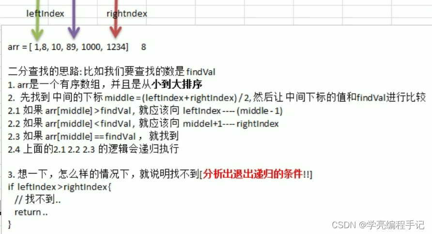
Thinking analysis of binary search method

腾讯的技术牛人们,是如何完成全面上云这件事儿的?

再突破!阿里云进入Gartner云AI开发者服务挑战者象限

Innovation strength is recognized again! Tencent security MSS was the pioneer of cloud native security guard in 2022

Identify and stop the process that's listening on port 8080 or configure this application

融云:让银行轻松上“云”

Opengauss database source code analysis series articles -- detailed explanation of dense equivalent query technology (Part 1)

Apache foundation officially announced Apache inlong as a top-level project
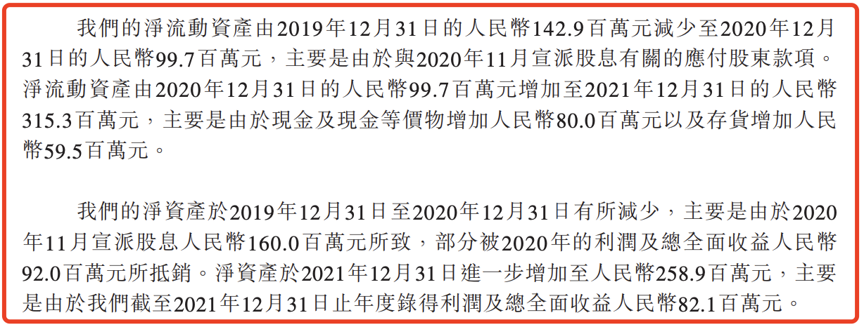
Shushulang passed the listing hearing: the gross profit margin of the tablet business fell, and the profit in 2021 fell by 11% year-on-year
随机推荐
Apache commons tool class
再突破!阿里云进入Gartner云AI开发者服务挑战者象限
聚焦:ZK-SNARK 技术
Improving efficiency or increasing costs, how should developers understand pair programming?
The evolution of social structure and capital system brought about by the yuan universe
How to select securities companies? Is it safe to open a mobile account?
Use of iscellstr function in MATLAB
Implementation of golang bubble sort code
创新实力再获认可!腾讯安全MSS获2022年度云原生安全守护先锋
Pytorch: saving and exporting models
提高效率 Or 增加成本,开发人员应如何理解结对编程?
Now I want to buy stocks. How do I open an account? Is it safe to open a mobile account?
golang gob实现网络数据的传输
Code examples of golang goroutine, channel and time
Golang write file code example
【历史上的今天】6 月 23 日:图灵诞生日;互联网奠基人出生;Reddit 上线
亚朵更新招股书:继续推进纳斯达克上市,已提前“套现”2060万元
golang goroutine、channel、time代码示例
泰山OFFICE技术讲座:使用字体斜体的四种情形
Code example of golang date time package: get age, zodiac and constellation based on birthday